background image

31

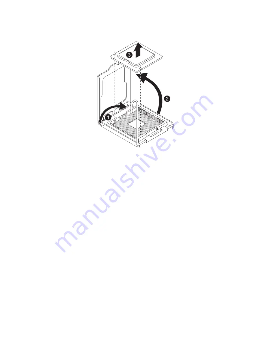
(3) Grasp the processor by its edges and lift it out of its socket.

6

Remove the new processor from its protective packaging. 

7

Install the new processor. 
(1) Hold the processor by its edges, then insert it in the socket.

Make sure that the alignment tabs on the socket fit the two 
notches located on the edges of the processor. The pins are 
keyed in such a way that you cannot install the processor in the 
wrong orientation without bending the pins.

(2) Close the retention plate.

Summary of Contents for GT110 Series

Page 1: ...GT110 Series User Guide GT110...

Page 2: ...Model Number Serial Number Purchase Date Place of Purchase 2009 All Rights Reserved Gateway GT110 Series User Guide Gateway GT110...

Page 3: ...he power cord to the AC power outlet Unplug the power cord before removing the power supply unit from the computer If the system has multiple sources of power disconnect power from the system by unplu...

Page 4: ...w anything to rest on the power cord Do not locate this product where people will walk on the cord If an extension cord is used with this product make sure that the total ampere rating of the equipmen...

Page 5: ...roduct was exposed to rain or water The product has been dropped or the case has been damaged The product exhibits a distinct change in performance indicating a need for service The product does not o...

Page 6: ...n check www lamprecycle org Tips and information for comfortable use Computer users may complain of eyestrain and headaches after prolonged use Users are also at risk of physical injury after long hou...

Page 7: ...t glasses or contact lenses glare excessive room lighting poorly focused screens very small typefaces and low contrast displays could stress your eyes The following sections provide suggestions on how...

Page 8: ...id looking at bright light sources such as open windows for extended periods of time Developing good work habits Develop the following work habits to make your computer use more relaxing and productiv...

Page 9: ...nt or relocate the receiving antenna Increase the separation between the device and receiver Connect the device into an outlet on a circuit different from that to which the receiver is connected Consu...

Page 10: ...nty Above all it provides no assurance that any item will work correctly in all respects with another item of Telepermitted equipment of a different make or model nor does it imply that any product is...

Page 11: ...such problems occur the user should NOT contact the telecom Fault Service 8 This equipment may not provide for the effective hand over of a call to another device connected to the same line 9 Under p...

Page 12: ...eless LAN and or Bluetooth only General This product complies with the radio frequency and safety standards of any country or region in which it has been approved for wireless use Depending on configu...

Page 13: ...ripherals 15 Turning on the system 16 Power on problems 17 Configuring the system OS 18 Turning off the system 19 3 System upgrades 21 Installation precautions 22 ESD precautions 22 Pre installation i...

Page 14: ...ion 61 Boot menu 63 Exit menu 64 5 System troubleshooting 65 Resetting the system 66 Initial system startup problems 67 Initial troubleshooting checklist 67 Hardware diagnostic testing 69 Checking the...

Page 15: ...1 System tour...

Page 16: ...ve bay Allows installation of additional storage devices 3 HDD activity indicator Indicates the status of a system hard drive blue 4 LAN status indicator Indicates the system network connection status...

Page 17: ...et Connect the system power cord here 2 Main power supply module Provides the system s main power supply 3 PS 2 mouse port Connects to a PS 2 mouse 4 PS 2 keyboard port Connects to a PS 2 keyboard 5 S...

Page 18: ...cts to an internet or intranet network 9 PCI slot covers Protect the vacant expansion slots 10 System fan Regulates the system airflow 11 Parallel port Connects to parallel devices No Component 1 Powe...

Page 19: ...5 4 HDD carriers 5 Mainboard 6 PCI slot lock 7 System fan No Component...

Page 20: ...1 System tour 6 System boards Mainboard No Code Description 1 PS 2 ports Connect to PS 2 mouse and keyboard 2 Serial port Connects to serial devices 3 Parallel port Connects to parallel devices...

Page 21: ...slot 12 24 pin ATX Power connector 13 SATA 1 SATA cable connector 14 SATA 0 SATA cable connector 15 SATA 3 SATA cable connector 16 SATA 2 SATA cable connector 17 SATA 5 SATA cable connector 18 SATA 4...

Page 22: ...1 System tour 8 26 PCI E 1 PCI E x8 slot 27 CPU_FAN CPU fan cable connector 28 8 pin ATX Power connector 29 SYS_FAN System fan cable connector No Code Description...

Page 23: ...clear the CMOS data to its default value by shorting the 2 3 pins BIOS recovery You may put the computer into BIOS recovery mode by shorting the 2 3 pins Jumper position Status 1 2 close Normal defau...

Page 24: ...can aid in problem diagnosis and troubleshooting Front panel LED indicators There are three LED indicators mounted on the front bezel Jumper position Status 1 2 close Enable BIOS recovery 2 3 close No...

Page 25: ...dicator Color State Representative Status 2 HDD activity Blue Flashing HDD access N A Off No access and no HDD fault 3 Power Blue On S0 Power on Blue Flashing 1 Hz with at 50 duty cycle S1 Sleep N A O...

Page 26: ...bps connection Off Port identification with 10 Mbps connection Green On 100 Mbps connection Green Flashing Port identification with 100 Mbps connection Yellow On 1 Gbps connection Yellow Flashing Port...

Page 27: ...2 System setup...

Page 28: ...ean and dust free Stable surface free from vibration Well ventilated and away from sources of heat Secluded from electromagnetic fields produced by electrical devices such as air conditioners radio an...

Page 29: ...uctions for each port Note Consult the operating system manual for information on how to configure the network setup Caution Do not route the power cord where it will be walked on or pinched by items...

Page 30: ...t a series of power on self test POST messages appears The POST messages indicate if the system is running well or not Note If the system does not turn on or boot after pressing the power button go to...

Page 31: ...outlet and to the power cord socket No power comes from the grounded power outlet Have an electrician check your power outlet Loose or improperly connected internal power cables Check the internal cab...

Page 32: ...e disc tray slides open insert the Gateway Smart Setup DVD with the label side of the disc facing upward Note When handling the disc hold it by the edges to avoid smudges or fingerprints 4 Press the d...

Page 33: ...user documentation To turn off the system via software 1 Press Ctrl Alt Delete on the attached keyboard or click Start on the Windows taskbar 2 Select Shut Down 3 Select Shut Down from the drop down m...

Page 34: ...2 System setup 20...

Page 35: ...3 System upgrades...

Page 36: ...side down Wear a wrist grounding strap and attach it to a metal part of the server before handling components If a wrist strap is not available maintain contact with the server throughout any procedu...

Page 37: ...ions Perform the steps below after installing a server component 1 See to it that all components are installed according to the described step by step instructions 2 Reinstall any expansion board s pe...

Page 38: ...erver before you can install upgrade components The left side panel is removable to allow access to the server s internal components Refer to the following sections for instructions Removing the side...

Page 39: ...Perform the pre installation instructions described on page 22 2 Remove the side panel described on page 24 3 Remove an available HDD carrier from the side of the chassis Press tabs together and pull...

Page 40: ...SAS cables to the new HDD 8 Observe the post installation instructions described on page 23 Installing a 5 25 storage device The two 5 25 device bays support a variety of storage devices for additiona...

Page 41: ...e installation instructions described on page 22 2 Remove the side panel described on page 24 3 Remove the 5 25 bay cover 1 and EMI protector 2 4 Slide the tool less bracket to the left to unlock the...

Page 42: ...bles 4 to the new 5 25 drive 7 Observe the post installation instructions described on page 23 To upgrade or replace a defective storage device 1 Perform the pre installation instructions described on...

Page 43: ...oard supports Intel Xeon 3000 Sequence and Pentium processors Observe the following guidelines when replacing or installing a processor The CPU socket must always be populated If no processor is insta...

Page 44: ...rewdriver to loosen the four HSF mounting pins 2 Once you have loosened all four mounting pins lift the HSF away from the mainboard 3 Disconnect the heat sink fan cable from the mainboard Use an alcoh...

Page 45: ...the new processor 1 Hold the processor by its edges then insert it in the socket Make sure that the alignment tabs on the socket fit the two notches located on the edges of the processor The pins are...

Page 46: ...he processor socket retention plate 2 Apply a thin layer of thermal interface material before installing the HSF Make sure that only a very thin layer is applied so that both contact surfaces are stil...

Page 47: ...3 3 Reconnect the HSF cable to its mainboard connector Refer to the Mainboard section on page 6 for the location of the HSF connectors 10 Observe the post installation instructions described on page 2...

Page 48: ...only approved 240 pin DDR2 unbufferred DIMM ECC modules in 1 GB or 2 GB capacities Use identical modules same specification for size speed and organization The minimum memory configuration is one DIMM...

Page 49: ...erred DIMM make sure to back up all important system files 1 Perform the pre installation instructions described on page 22 2 Lay the server on its side components showing 3 Remove the DIMM 1 Press th...

Page 50: ...lot 3 If necessary open the holding clips of the selected DIMM slot 4 Remove the new DIMM from its protective packaging handling it by the edges 5 Install the DIMM 1 Align the DIMM so that the notch o...

Page 51: ...M is not properly inserted 6 Observe the post installation instructions described on page 23 The system automatically detects the amount of memory installed Run the BIOS setup to view the new value fo...

Page 52: ...th One PCI Express x8 slot x4 bandwidth Two PCI 32 bit 5 V slots To install an expansion card 1 Perform the pre installation instructions described on page 22 2 Remove the side panel described on page...

Page 53: ...he slot cover and store it for reassembly later Caution Do not discard the slot cover If the expansion card is removed in the future the slot cover must be reinstalled to maintain proper system coolin...

Page 54: ...bracket securing the card into place Connect the necessary cables to the expansion card as required 6 Observe the post installation instructions described on page 23 When you turn on the system the BI...

Page 55: ...4 System BIOS...

Page 56: ...etup message to make changes to the BIOS setup Note If you repeatedly receive Run Setup messages the battery may be bad In this case the system cannot retain configuration values in CMOS Ask a qualifi...

Page 57: ...ar correspond to the six primary BIOS Setup menus namely Main Advanced Security Server Boot Exit In the descriptive table following each of the menu screenshots settings in boldface are the default an...

Page 58: ...le Enter key Display a submenu screen Note Availability of submenu screen is indicated by a Esc If you press this key On one of the primary menu screens the Exit menu displays On a submenu screen the...

Page 59: ...Sets the date following the weekday month day year format BIOS Version Version number of the BIOS Setup Utility BIOS Date Date when the BIOS Setup Utility was created CPU Type CPU Speed CPU Count Tec...

Page 60: ...stem BIOS 46 Advanced menu The Advanced menu display submenu options for configuring the function of various hardware components Select a submenu item then press Enter to access the related submenu sc...

Page 61: ...clock the more instructions the CPU can execute per second Processor CPUID Processor ID number Processor L2 Cache Processor second level cache size detected during POST C1 Enhanced Mode Reduce the cor...

Page 62: ...the latency associated with memory reads Enabled Disabled Adjacent Cache Line Prefetch Feature that reduces cache latency by making the next cache line immediately available if the processor requires...

Page 63: ...tected during POST Extended Memory Total size of extended memory detected during POST DIMM Status The size of memory installed on each of the DDR2 Unbufferred DIMM slots Memory Retest Select whether t...

Page 64: ...n LAN PME Allows user to determine the action of the system when LAN PME wake up event occurs Enabled Disabled Wake On Ring Allows user to determine the action of the system when the modem rings Enabl...

Page 65: ...ameter Description Option CPU Motherboard DDR Temperature Display the current CPU Motherboard and DDR temperature Voltage Monitor Detects the system s voltage status Fan Monitor Display the current CP...

Page 66: ...on ROM When enabled this setting will initialize the device expansion ROM for the related PCI slot Enabled Disabled Onboard LAN Controller Enables or disables the onboard LAN Controller Enabled Disabl...

Page 67: ...isables the Serial ATA Enabled Disabled Native Mode Operation Sets the Native Mode Operation Auto Serial ATA SATA RAID Enable Enables or Disables the SATA RAID Enabled Disabled SATA AHCI Enable Enable...

Page 68: ...ort 3F8 IRQ4 2F8 IRQ3 3E8 IRQ4 2E8 IRQ3 Serial port B Enables or disables the serial port B Enabled Disabled Base I O address Base I O address and IRQ setting for the selected serial port 3F8 IRQ4 2F8...

Page 69: ...T Error Pause Select whether to pause POST when a boot up error is detected All Errors No Errors All but Keyboard AC LINK Select mode of operation if power loss occurs Power On Stay Off Last State Num...

Page 70: ...ngs in the Setup Utility User password Entering this password will allow a user to enter the Setup menus but not have the rights to make changes Power on password When the Password on Boot field is en...

Page 71: ...up down keys to select a password parameter Set Supervisor Password or Set User Password then press Enter 2 Type the original password then press Enter 3 Type a new password then press Enter 4 Retype...

Page 72: ...arameter Set Supervisor Password or Set User Password then press Enter 2 Enter the current password then press Enter 3 Press Enter twice without entering anything in the new and confirm password field...

Page 73: ...re versions Press Enter to access the related submenu Console Redirection Displays console redirection related settings Press Enter to access the related submenu System Management The System Managemen...

Page 74: ...4 System BIOS 60 window are non configurable...

Page 75: ...le redirection enables users to manage the system from a remote location Onboard COM A Onboard COM B Disabled Baud Rate Select the baud rate for console redirection 300 1200 2400 9600 19 2K 38 4K 57 6...

Page 76: ...4 System BIOS 62 Continue CR After POST Select whether to enable console redirection after POST On Off Parameter Description Options...

Page 77: ...drive priority during system boot up BIOS setup will display an error message if the drive specified is not bootable By default the server searches for boot devices in the following order 1 Optical di...

Page 78: ...cards changes made and close the BIOS setup Load Setup Defaults Loads the default settings for all BIOS setup parameters Setup Defaults are quite demanding in terms of resources consumption If you are...

Page 79: ...5 System troubleshooting...

Page 80: ...ystem using one of the methods below Perform Purpose To do this Soft boot reset To clear the system memory and reload the operating system Press Ctrl Alt Del Cold boot reset To clear the system memory...

Page 81: ...d secured Did you press the system power button to turn the server on power on indicator should be lit green Are all device drivers properly installed Are hard disks properly formatted and configured...

Page 82: ...5 System troubleshooting 68 e g two add in boards sharing the same interrupt...

Page 83: ...rectly connected to the system 5 Turn on the display monitor 6 Set the display brightness and contrast controls to at least two thirds of their maximum range Refer the documentation that came with you...

Page 84: ...wing Make sure the power supply module is properly installed Make sure the power cord is connected correctly Make sure that the wall outlet has power Test it by plugging in another device Make sure th...

Page 85: ...ive cannot read a disc Do the following Make sure you are using the correct type of disc Make sure the disc is properly seated in the drive Make sure the disc is unscratched and free of any contaminan...

Page 86: ...software to see if the problem is with the copy you are using If the other version runs correctly on the system contact your vendor about the defective software No characters appear on the display mon...

Page 87: ...using the onboard video controller 2 Verify that the add in video controller card is fully seated in its slot 3 Reboot the system for the changes to take effect 4 If there are still no characters on t...

Page 88: ...5 System troubleshooting 74...

Page 89: ...Appendix A Server management tools...

Page 90: ...r and security settings Go to the BIOS setup chapter on page 41 for details Onboard SATA RAID Configuration Utility Use any of these utilities to configure RAID for the system hard drives LSI MegaRAID...

Page 91: ...all open applications then restart the server 2 During POST press F2 to access the BIOS Setup Utility 3 Select the Advanced SATA Configuration submenu 4 Change the setting of the SATA RAID Enable fiel...

Page 92: ...sired RAID level and press Enter to select Strip Size 5 Set the size from 4KB to 128KB Then press Enter to set Capacity 6 Set disk capacity and press Enter to create the volume 7 You will be prompted...

Page 93: ...Appendix B LSI RAID configuration...

Page 94: ...faults from No to Yes then click on submit 3 Exit the configuration utility and press Ctrl Alt Del to reboot the server Creating a RAID volume 1 Launch the configuration menu 2 Select Configuration Wi...

Page 95: ...igning a Hot Spare Disk 1 Launch the configuration menu 2 Select a free disk marked as UNCONF GOOD and listed under Physical Drives 3 Select Make Global Dedicated HSP or Make Dedicated HSP and click o...

Page 96: ...Appendix B LSI RAID configuration 82...

Page 97: ...55 boot up sequence 63 C CMOS RAM 42 console redirection 61 D DVD ROM drive location 2 troubleshooting 71 E electrostatic discharge see ESD pre cautions 22 expansion card I O interface 38 install 38...

Page 98: ...side panel remove 24 supervisor password 56 system boards mainboard 6 system fan location 5 system passwords change 57 power on password 56 remove 58 set 57 supervisor password 56 user password 56 sys...

Page 99: ...85 U USB ports front 2 rear 4 troubleshooting 72 user password 56...

Page 100: ...86...

Reviews: