- 44 -
MaxVIEW
MaxVIEW
MaxVIEW
MaxVIEW
400 Components.
400 Components.
400 Components.
400 Components.
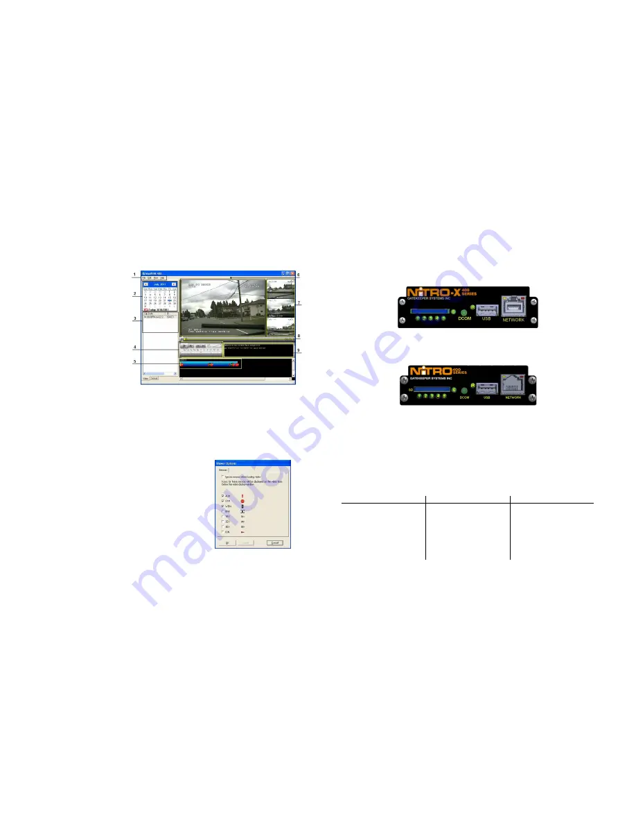
1.
Standard Windows Menu
bar.
2.
Calendar feature. Dates
in bold are quick view
enabled. The date high-
lighted denotes the file
currently being viewed.
3.
Clip List. Video available
from the currently
displayed Date.
4.
Video Control Panel.
Controls Playback speed;
forward/reverse and
Speed. Volume can be
muted or un-muted.
5.
Time Graph and Sensor
display. Shows the
currently active sensors. Also used for marking and saving video and still image clips.
6.
Playback Window. Displays the currently chosen camera as the primary view.
7.
Thumbnail Images. Display additional camera views available. To view as the focus click on a
thumbnail and it will swap positions with the camera view currently in the Playback Window (6).
8.
Scrubber Bar. Allows Fast-Forward/Reverse to a specific time.
9.
Subtitle Information. Displays information which has been configured on the NiTRO
400 or
NiTRO-X
400
Figure 25 : MaxVIEW
Window Definitions.
Displaying Sensors.
Displaying Sensors.
Displaying Sensors.
Displaying Sensors.
MAXVIEW
400 can display up-to 3 sensors, ALM (Alarm);
STP (Stop); and WRN (Warning). These sensors can be
turned On or Off as display items within MAXVIEW
.
To select which sensors to have display in the Time Graph and
Sensor display (#5 in Figure 25) click on the Edit menu in
MaxVIEW
and select Options.
Select which of these you want to display in the Time Graph
and Sensor display and click Apply and then OK.
Please N
Please N
Please N
Please Note:
ote:
ote:
ote: Currently the three available options ALM, STP
and WRN are the only active sensors. BRK; 1EX; 2EX; 3EX
and IGN are reserved for future development.
Figure 26: Displaying Sensors.
- 25 -
System Features.
System Features.
System Features.
System Features.
N
N
N
NiTRO
iTRO
iTRO
iTRO----X
X
X
X
400 Series
400 Series
400 Series
400 Series Front View.
Front View.
Front View.
Front View.
Figure 4 : Front View Description.
The NiTRO
401 / 404 share a common front interface.
NiTRO
NiTRO
NiTRO
NiTRO
401 / 404 Front View.
401 / 404 Front View.
401 / 404 Front View.
401 / 404 Front View.
Figure 5: Front View Description.
1 Power Indicator
2 Run Indicator
3 Alarm Indicator
4 SD Card Present Indicator
5 System Status Indicator
6 Stop Button. Press and hold until System Status Indicator is out before removing SD Card.
IR
Communicates with the supplied Remote Control.
USB
Reserved for future development.
RJ45 NET
Allows an RJ45 connector to be inserted.
F
F
F
Front LED Status Definitions.
ront LED Status Definitions.
ront LED Status Definitions.
ront LED Status Definitions.
POWER LED (1)
POWER LED (1)
POWER LED (1)
POWER LED (1)
RUN LED (2)
RUN LED (2)
RUN LED (2)
RUN LED (2)
DEFINITION
DEFINITION
DEFINITION
DEFINITION
Always On
Flashing
NiTRO
or NiTRO-X
is ON
and is either booting up, or, in
Record mode.
Flashing Alternatively with
RUN
Flashing Alternatively with
POWER
NiTRO
or NiTRO-X
is in
Standby Mode waiting for
ignition signal. Ignition line is
off
Flashing Together with RUN
Flashing Together with
Power Off Delay (Record


