background image

VRT Hydraulic Drive 

– Monitor Operation 

Page 66 

05/06 

RUN/HOLD Function 


  When the monitor is switched on, the 

screen  will  display  ‘

UNIT  ON  HOLD

’.  This 

shows  that  the  metering  system  is 
disengaged  and  will  not  operate  even  if  it 
receives  a  ground  speed  feedback.  The 
operator  can  change  this  status  by  simply 
pressing the ‘RUN/HOLD’ key.  

 
Once  ‘OFF  HOLD’  the  metering 

system  will  operate  when  it  senses  a 
ground speed, and if the fan speed is above 
the ‘fan low alarm’ point. 

 
The  trip  functions  will  start  recording 

the area and rates of application. All alarms 
will  become  active  to  monitor  the  seeder’s 
operation. 

 
To  stop  the  metering  system  simply 

pre

ss the ‘RUN/HOLD’ key and the monitor 

will go back to its ‘

UNIT ON HOLD

’ status. 


PRIME Function 


The  ‘

PRIME

’  function  allows  the 

operator  to  start  the metering  system  while 
the  seeder  is  stationary.  This  can  be  a 
useful  tool  if  in  the  middle  of  a  run  or  to 
ensure correct product flow.  

 
It is possible to alter the prime functions 

run time by changing the preset value in the 
OPTIONS menu screen. 

 
The prime function can be used similar 

to the ‘RUN/HOLD’ key. The operator can be 
stationary  and  on  hold.  By  pressing  the 

PRIME

’  soft  key  and  waiting  3  seconds  to 

allow seed and fertiliser to reach the sowing 
boots  before  driving  off,  the  operator  can 
ensure complete ground coverage. 


 When  the  monitor  registers  a  ground 

speed  before  the  prime  function  stops  the 
mo

nitor will come ‘OFF HOLD’ automatically. 

To  stop  the  metering  system  simply  press 
the ‘RUN/HOLD’ function key. 


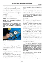
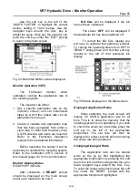
Fig.V6     Prime and Run/Hold key. 


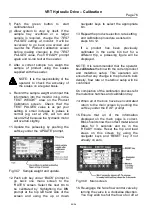
Fig.V7  Main screen showing a typical display while operating. 

Summary of Contents for SR Series

Page 1: ...er this manual or part thereof may be reproduced or published without the prior permission of A F Gason Pty Ltd 1800 2000 SR SERIES AIR SEEDER OPERATOR S MANUAL Covering the 1860 1880 90 2120 50 Model...

Page 2: ...Page Intentionally Blank...

Page 3: ...34 Method B preferred 37 Method C Wheel Circumference 38 Calibrating a 3 Bin Seeder 40 Variator Setting Guide 41 Calibration Handle Turns 56 Area Rate Chart 57 Converting lb acre to kg ha 58 Planting...

Page 4: ...Cover Plates 110 High Low Sprocket Ratio 111 Blocking Air Flow 111 Metering Oats 112 Fitting Broad Beans Metershaft Assy 112 Bearing Replacement in Nose Assy 113 Hydraulic System 114 Tractor Requirem...

Page 5: ...table to a variety of implements to perform different tillage practices The Gason metering system is a positive and accurate method of placing seed and fertilizer into the air stream The system is cap...

Page 6: ...Introduction Page 2 02 07 Fig 2 2150FT Series Air Seeder with Auger and rear walkway optional Fig 3 2150RT Series Air Seeder...

Page 7: ...d by either a ground wheel ground drive seeder or hydraulic motor VRT equipped Seeder As the ground wheel rotates so too does the metering system The metering system can be disengaged or engaged at th...

Page 8: ...uring turning which will help extend the life of the machine The trailer has also been designed to withstand the high loads exerted on the frame while pulling the implement In both cases the seeders h...

Page 9: ...quality components and will require minimal maintenance The system has been designed to operate in a harsh environment It is fitted with a check valve to prevent damage if incorrectly connected The bl...

Page 10: ...o air leaks when blower is operating 10 Check distribution hoses for damage or kinks especially after operating the wing fold system on the implement General Safety Conditions DO NOT ride on the machi...

Page 11: ...n the bins The 1860 2150 model seeders will require a third front sling for lifting Ensure you have safe lifting equipment with the correct capacity before attempting to hoist the machine Fig G4 2150R...

Page 12: ...capacity 6200 6200 L By weight Front bin wheat 2340 2340kg Rear bin super 3990 3990kg Total weight 6330 6330kg wheat 850kg 1000 litres super 1160kg 1000 litres Bin Capacity 3 Bin Equal Middle Rear Bin...

Page 13: ...r and options Bin Capacity 2 Bin By volume Front bin 44 3600 3600 L Rear bin 56 4600 4600 L Total capacity 8200 8200 L By weight Front bin wheat 3060 3060kg Rear bin super 5330 5330kg Total weight 839...

Page 14: ...and options Bin Capacity 2 Bin By volume Front bin 44 4050 4050 L Rear bin 56 5150 5150 L Total capacity 9200 9200 L By weight Front bin wheat 3440 3440kg Rear bin super 5970 5970kg Total weight 9410...

Page 15: ...luding an Auger Bin Capacity 2 Bin By volume Front bin 44 5500 5500 L Rear bin 56 6900 6900 L Total capacity 12 400 12 400L By weight Front bin wheat 4675 4675kg Rear bin super 8000 8000kg Total weigh...

Page 16: ...l not including an Auger Bin Capacity 1 Tank 2 X2500L 2 Bin By volume Non packed Front tank 41 5000 L 5000 L Middle bin 26 3150 L 3150 L Rear bin 33 3950 L 3950 L Total capacity 12 100 12 100L By weig...

Page 17: ...30 Rear tyres 900 60 R32 900 60 R32 Type Front tyres R1 Gripster Rear Tyres R1 Gripster Tyre Recommended Pressure kPa psi 23 1 30 8pr Gripster 140 20 900 60 R32 Radial 240 35 Hydraulics Fan Motor type...

Page 18: ...s wheat 850kg 1000 litres super 1160kg 1000 litres Wheels Size 2150FT 2150RT Front tyre quad 23 1 30 Rear tyres 900 60 R32 900 60 R32 Type Front tyres R1 Gripster Rear Tyres R1 Gripster Tyre Recommend...

Page 19: ...911L 4744L 3378L 1916L 1263L FRONT 5534L 3766L 2672L 1519L 1005L MIDDLE 3177L 2295L 1746L 1049L 719L REAR 3980L 2695L 1877L 1113L 789L FRONT 5000L MIDDLE 3177L 2295L 1746L 1049L 719L REAR 3980L 2695L...

Page 20: ...3 cu Ft 8 00 U 1 L 0 0274962 UK Bushels1 UK Bushel 36 369 L 1 L 0 0283785 US Bushels 1 US Bushel 35 2379 L TORQUE 1 Nm 0 7375624 lbft 1 lbft 1 3558175 Nm FORCE 1 lbf 4 4482 N 1N 0 22481 lbf PRESSURE 1...

Page 21: ...lts 1 10 for black oxide finished bolts 0 81 for M20x2 5P Tine Toolbar Hardware It is necessary that all bolts be tightened to the correct recommended assembly torque lbf ft Nm lbf ft Nm lbf ft Nm 7 1...

Page 22: ..._ Telephone Number _________________ Machine Model No __________________ Date Machine Purchased ____________ Serial No _________________________ 1118 Serial No tag at left front of trailer frame Subje...

Page 23: ...SPARE PARTS RECORD Page 19 10 09 PART No DESCRIPTION QTY COST DATE...

Page 24: ...bolted to the extension beams The A frame pull is pinned in 2 places to the cross beam The spring mechanism should be fitted to hold the A frame pull off the ground to allow the implement to be manoeu...

Page 25: ...ort up through the square tube slide on the outside of the arm Fit the small pin at the base of the spring mechanism to hold arm horizontal Repeat for second arm 1339 Fig A6 Spring Support Step 5 Join...

Page 26: ...paced to clear tines and other implement structure but should be symmetrical about the implement centreline refer Fig A10 The cross beam can then be bolted to the extension beams Hydraulic hoses can b...

Page 27: ...t Hitch to Suit 1880 90RT CTC Control Traffic Castor Similar to the 1860RT CTC hitch the A frame on the 1880 90RT CTC model uses 2 support springs to hold the A frame up to allow easy connection and d...

Page 28: ...terbox Assembly Check all Wheel Nuts Wheel nuts can work loose in transportation and should be checked before towing Once the seeder is operating the wheel nuts should again be checked until they have...

Page 29: ...ders Refer to the Hydraulic System section in this manual for further details Distribution System Introduction The distribution system consists of primary secondary and tertiary stages Components for...

Page 30: ...Assembly Instructions Page 26 10 09 Fig A15 Distribution Layout...

Page 31: ...ll occur if the tertiary hoses rise or lay flat when leaving the secondary heads Fig A16 Typical fall on tertiary hose When choosing a secondary head port to attach the tertiary hose the installer sho...

Page 32: ...terbox and drive system including the nose bearing on the metershaft assembly 6 Meterbox hatches fitted Ground Drive Metering System Cont 7 Metering system turns freely 8 Variator adjustment operates...

Page 33: ...ued if required In a dangerous manner that may threaten the safety of any person Tips to remember when towing the Air Seeder 1 If towing long distances disconnect the drive system by removing the chai...

Page 34: ...er to the Blower section You are now ready to begin your seeding operation Filling the Seeder s Bins In most cases operators will tend to fill the front bin with seed and the rear bin with fertilizer...

Page 35: ...ers a calibration procedure performed To obtain basic information and the preset values used on your specific model supplied refer to either the Ground Drive Monitor Operation section page 32 or the V...

Page 36: ...de activated When the clutch switch is turned on the message MONITOR OFF HOLD will appear once to tell the operator that normal seeding operations have commenced The monitor will now operate the trip...

Page 37: ...ow and high pressure alarm to warn against a cap or hose coming loose or a blockage while conveying material Clutch Switch A separate clutch switch is supplied that can be mounted independently from t...

Page 38: ...this style of seeder is dependent upon a correct wheel diameter for its operating accuracy If this diameter is altered e g incorrect tyre fitted wrong tyre pressure or extreme ground conditions inaccu...

Page 39: ...h has been fitted to a meter shaft Step 4 Rotate calibration handle 10 or 20 turns anti clockwise follow arrow For high rates use 10 turns and for normal winter rates use 20 turns Fig C5 Fig C5 Calibr...

Page 40: ...convert lb acre to kg ha Step 7 Adjust setting to obtain correct application rate and re test To adjust the setting simply unlock the handle rotating the handle anti clockwise and either increase or d...

Page 41: ...eed to retest the system following steps 4 and 5 Example 1 An application rate of 60 kg ha of wheat is desired on a planting width of 10 0 metres using a 4 outlet meterbox with 3 meterwheels fitted Fr...

Page 42: ...from 1 0 to 0 95 to obtain 4 5 kg ha and retest NOTE It is not recommended to run below 0 75 setting on the variator adjustment assembly Fit metershaft reduction plates to the metershaft assembly to...

Page 43: ...50 metres Implement sowing width in this case is 13 75 metres Therefore the wheel circumference is 21 5 metres 5 rotations 4 3 metres wheel circ 500 x sprocket ratio sowing width x wheel circ handle t...

Page 44: ...120 seeder 8 310 2150 seeder 8 809 Example 1 Using example 1 on page 39 to determine the wheel circumference for a 1850 seeder half full of product the field figure was 4 3metres Therefore the revised...

Page 45: ...across and up the chart we can see that the recommended setting is 2 4 This figure is a guide only and will need to be checked by the normal calibrating procedure VARIATOR SETTING GUIDE INDICATIVE ONL...

Page 46: ...NTING WIDTH metres SR Meterbox 4 Meterwheels fitted 100 3 1 4 2 5 2 6 2 7 3 8 3 9 4 APPLICATION 80 2 5 3 3 4 2 5 0 5 8 6 7 7 5 8 3 9 2 RATE kg ha 60 1 9 2 5 3 1 3 7 4 4 5 0 5 6 6 2 6 9 PER BIN 40 1 2...

Page 47: ...4 Meterwheels fitted 160 3 7 4 9 6 1 7 3 8 5 9 8 120 2 7 3 7 4 6 5 5 6 4 7 3 8 2 9 2 100 2 3 3 1 3 8 4 6 5 3 6 1 6 9 7 6 8 4 APPLICATION 80 1 8 2 4 3 1 3 7 4 3 4 9 5 5 6 1 6 7 RATE kg ha 60 1 4 1 8 2...

Page 48: ...2 5 0 5 7 6 4 7 1 7 8 120 1 6 2 1 2 7 3 2 3 7 4 2 4 8 5 3 5 8 100 1 3 1 8 2 2 2 7 3 1 3 5 4 0 4 4 4 9 APPLICATION 80 1 1 1 4 1 8 2 1 2 5 2 8 3 2 3 5 3 9 RATE kg ha 60 0 8 1 1 1 3 1 6 1 9 2 1 2 4 2 7 2...

Page 49: ...els fitted 160 5 4 7 3 9 1 120 4 1 5 4 6 8 8 2 9 5 100 3 4 4 5 5 7 6 8 7 9 9 1 APPLICATION 80 2 7 3 6 4 5 5 4 6 4 7 3 8 2 9 1 RATE kg ha 60 2 0 2 7 3 4 4 1 4 8 5 4 6 1 6 8 7 5 PER BIN 40 1 4 1 8 2 3 2...

Page 50: ...4 9 5 120 2 4 3 2 3 9 4 7 5 5 6 3 7 1 7 9 8 7 100 2 0 2 6 3 3 3 9 4 6 5 3 5 9 6 6 7 2 APPLICATION 80 1 6 2 1 2 6 3 2 3 7 4 2 4 7 5 3 5 8 RATE kg ha 60 1 2 1 6 2 0 2 4 2 8 3 2 3 6 3 9 4 3 PER BIN 40 0...

Page 51: ...ING WIDTH metres SR Meterbox 4 Meterwheels fitted 120 5 9 7 9 9 8 100 4 9 6 6 8 2 9 8 APPLICATION 80 3 9 5 2 6 6 7 9 9 2 RATE kg ha 60 2 9 3 9 4 9 5 9 6 9 7 9 8 8 9 8 PER BIN 40 2 0 2 6 3 3 3 9 4 6 5...

Page 52: ...eels fitted 160 5 7 7 6 9 4 120 4 2 5 7 7 1 8 5 100 3 5 4 7 5 9 7 1 8 3 9 4 APPLICATION 80 2 8 3 8 4 7 5 7 6 6 7 6 8 5 9 4 RATE kg ha 60 2 1 2 8 3 5 4 2 5 0 5 7 6 4 7 1 7 8 PER BIN 40 1 4 1 9 2 4 2 8...

Page 53: ...120 3 7 4 9 6 2 7 4 8 6 9 9 APPLICATION 100 3 1 4 1 5 1 6 2 7 2 8 2 9 3 RATE kg ha 80 2 5 3 3 4 1 4 9 5 8 6 6 7 4 8 2 9 1 PER BIN 60 1 9 2 5 3 1 3 7 4 3 4 9 5 6 6 2 6 8 50 1 5 2 1 2 6 3 1 3 6 4 1 4 6...

Page 54: ...140 2 5 3 3 4 2 5 0 5 8 6 7 7 5 8 4 9 2 120 2 1 2 9 3 6 4 3 5 0 5 7 6 4 7 2 7 9 APPLICATION 100 1 8 2 4 3 0 3 6 4 2 4 8 5 4 6 0 6 6 RATE kg ha 80 1 4 1 9 2 4 2 9 3 3 3 8 4 3 4 8 5 3 PER BIN 60 1 1 1 4...

Page 55: ...tres SR Meterbox 4 Meterwheels Large Seeds fitted 180 3 9 5 2 6 5 7 8 9 1 140 3 0 4 1 5 1 6 1 7 1 8 1 9 1 120 2 6 3 5 4 3 5 2 6 1 6 9 7 8 8 7 9 5 APPLICATION 100 2 2 2 9 3 6 4 3 5 1 5 8 6 5 7 2 8 0 RA...

Page 56: ...3 4 3 8 4 1 6 8 10 12 14 16 18 20 22 PLANTING WIDTH metres SR Meterbox 4 Meterwheels fitted 180 3 9 5 2 6 5 7 8 9 1 10 4 140 3 0 4 0 5 1 6 1 7 1 8 1 9 1 120 2 6 3 5 4 3 5 2 6 1 6 9 7 8 8 7 9 5 100 2...

Page 57: ...1 4 1 7 1 9 2 1 2 3 6 8 10 12 14 16 18 20 22 PLANTING WIDTH metres SR Meterbox 4 Meterwheels fitted 6 5 1 0 1 4 1 7 2 1 2 4 2 7 3 1 3 4 3 8 5 5 0 9 1 2 1 5 1 7 2 0 2 3 2 6 2 9 3 2 APPLICATION 5 0 8 1...

Page 58: ...8 2 1 2 3 6 8 10 12 14 16 18 20 22 PLANTING WIDTH metres SR Meterbox 4 Meterwheels fitted 12 1 9 2 5 3 1 3 8 4 4 5 0 5 7 6 3 6 9 8 1 3 1 7 2 1 2 5 2 9 3 4 3 8 4 2 4 6 APPLICATION 7 1 1 1 5 1 8 2 2 2...

Page 59: ...heels fitted 12 3 1 4 1 5 1 6 1 7 2 8 2 9 2 10 2 6 3 4 4 3 5 1 6 0 6 8 7 7 8 5 9 4 8 2 0 2 7 3 4 4 1 4 8 5 5 6 1 6 8 7 5 APPLICATION 7 1 8 2 4 3 0 3 6 4 2 4 8 5 4 6 0 6 6 RATE kg ha 6 1 5 2 0 2 6 3 1...

Page 60: ...10 3 37 6 10 5 36 7 10 8 35 8 11 0 35 0 11 3 34 2 11 5 33 5 11 8 32 8 12 0 32 1 12 3 31 4 12 5 30 8 12 8 30 2 13 0 29 6 13 3 29 0 PLANTING WIDTH m 1 20th Hectare 13 5 28 5 13 8 28 0 14 0 27 5 14 3 27...

Page 61: ...0 4 2 5 4 6 6 7 8 9 0 10 11 13 14 15 8 2 4 4 0 5 6 7 2 8 8 10 12 14 15 17 18 20 10 3 0 5 0 7 0 9 0 11 13 15 17 19 21 23 25 12 3 6 6 0 8 4 11 13 16 18 20 23 25 28 30 14 4 2 7 0 9 8 13 15 18 21 24 27 2...

Page 62: ...36 0 40 4 38 0 42 6 40 0 44 8 42 0 47 1 44 0 49 3 46 0 51 6 48 0 53 8 50 0 56 1 52 0 58 3 54 0 60 5 56 0 62 8 lb acre kg ha 58 0 65 0 60 0 67 3 62 0 69 5 64 0 71 7 66 0 74 0 68 0 76 2 70 0 78 5 72 0 8...

Page 63: ...Ground Drive Calibration Page 59 05 06 OTHER DETAILS APPLICATION RATE VARIATOR SETTING METERWHEEL REDUCTION PLATE SPROCKET RATIO BULK DENSITY MATERIAL DATE PLANTING DETAIL REFERENCE CHART...

Page 64: ...Ground Drive Calibration Page 60 05 06 OTHER DETAILS APPLICATION RATE VARIATOR SETTING METERWHEEL REDUCTION PLATE SPROCKET RATIO BULK DENSITY MATERIAL DATE...

Page 65: ...d setting This method of adjustment will ensure that there is no slack in the cable Fig MD2 Variator Adjustment 2 bin All of the main bins metering system can be set from the one station at different...

Page 66: ...when set at maximum should rotate 1 turn for every 4 turns of the input shaft You will need to mark the shaft or sprocket and have someone watch the input shaft side while the person turning the calib...

Page 67: ...tor shaft and the meterwheel shaft 2 Using an allen key loosen the grub screws that retain the nylon sprockets Two screws per sprocket 3 Remove both sprockets and swap their location This will effecti...

Page 68: ...operator how to calibrate the seeder when in the field Farmscan have also supplied an operator s manual with the monitor This manual covers relevant information for the control system and its operati...

Page 69: ...CAL After calibration a READY prompt should be displayed on the main screen under each material to be sown NO CAL will be displayed if the bin has not been calibrated The status OFF will be displayed...

Page 70: ...ts UNIT ON HOLD status PRIME Function The PRIME function allows the operator to start the metering system while the seeder is stationary This can be a useful tool if in the middle of a run or to ensur...

Page 71: ...section in this manual for further explanation p93 SAFETY VRT The VRT seeder uses hydraulic motors to turn the metering system The hydraulic motors which are mounted on the left hand side of each mete...

Page 72: ...a monitor and pod system that have no stored values for your specific air seeder Setup Procedure 1 Go to the SETUP screen via the MENU screen by highlighting the appropriate prompt and pushing the CA...

Page 73: ...reen Refer ALARMS Settings section beginning this page 10 Set the specific machine settings in the MACHINE screen Refer MACHINE Settings on page 70 The monitor is now ready for operation The next step...

Page 74: ...alue when actually seeding if a difference between the tractor s ground speed and the seeder s displayed speed exists Wheel factor can be affected by the tyres circumference Variations in ground hardn...

Page 75: ...b can be used to control the flow of hydraulic oil to each motor Simply undo the rear locking knob and rotate the front thumb knob as you would a tap anti clockwise to open the valve You will need to...

Page 76: ...the fan s flow control valve The seeder should now be ready for operation When you engage the hydraulics for the seeder at the tractor you will not only start the fan but rotate the metering system It...

Page 77: ...5 41 38 36 33 31 30 28 27 25 24 23 22 14 40 37 34 32 30 29 27 26 24 23 22 21 14 5 38 35 33 31 29 28 26 25 24 23 22 21 15 37 34 32 30 28 27 25 24 23 22 21 20 15 5 36 33 31 29 27 26 24 23 22 21 20 19 1...

Page 78: ...br ra at ti io on n P Pr ro oc ce ed du ur re e 1 Change meterbox settings to suit product and application rate being sown Some changes may need to be made to the meterbox before material is placed in...

Page 79: ...tter c When complete push the soft key under the READY prompt before leaving the cab Test pulses will now be displayed as zero and will record feedback from the seeder Fig VC4 Product Calibration Scre...

Page 80: ...e menu screen to the RATES screen Select the next bin to be calibrated by highlighting the BIN prompt at the top left hand side of the screen and using the up or down navigator keys to select the appr...

Page 81: ...ve metering system is capable of metering products at very low rates eg 3kg ha of canola through to extremely high rates 200kg ha and greater of fertiliser The hydraulic motors that rotate the metersh...

Page 82: ...go to the high sprocket ratio SPROCKET RATIO SELECTION GUIDE INDICITIVE ONLY MATERIAL OATS MATERIAL BULK DENSITY 590 kg cubic meter METERBOX SETTINGS REMOVE METERSHAFT COVER PLATE 80 HIGH HIGH HIGH HI...

Page 83: ...IGH HIGH HIGH HIGH HIGH HIGH 60 LOW LOW HIGH HIGH HIGH HIGH HIGH HIGH HIGH HIGH HIGH HIGH 40 LOW LOW LOW LOW LOW HIGH LOW HIGH HIGH HIGH HIGH HIGH 20 LOW LOW LOW LOW LOW LOW LOW LOW LOW LOW LOW LOW 8...

Page 84: ...GH HIGH HIGH HIGH HIGH 80 LOW HIGH HIGH HIGH HIGH HIGH HIGH HIGH HIGH HIGH HIGH HIGH 60 LOW LOW LOW LOW HIGH HIGH HIGH HIGH HIGH HIGH HIGH HIGH 40 LOW LOW LOW LOW LOW LOW LOW LOW HIGH LOW HIGH HIGH 8...

Page 85: ...H HIGH HIGH HIGH HIGH HIGH HIGH HIGH HIGH HIGH HIGH 60 LOW HIGH HIGH HIGH HIGH HIGH HIGH HIGH HIGH HIGH HIGH HIGH 40 LOW LOW LOW LOW LOW HIGH HIGH HIGH HIGH HIGH HIGH HIGH 8 10 12 8 10 12 8 10 12 8 10...

Page 86: ...W HIGH HIGH HIGH HIGH HIGH HIGH HIGH HIGH HIGH HIGH HIGH 40 LOW LOW LOW LOW HIGH HIGH HIGH HIGH HIGH HIGH HIGH HIGH 20 LOW LOW LOW LOW LOW LOW LOW LOW LOW LOW LOW HIGH 10 LOW LOW LOW LOW LOW LOW LOW L...

Page 87: ...GH HIGH HIGH HIGH HIGH HIGH HIGH 40 LOW LOW LOW LOW HIGH HIGH HIGH HIGH HIGH HIGH HIGH HIGH 20 LOW LOW LOW LOW LOW LOW LOW LOW LOW LOW LOW LOW 10 LOW LOW LOW LOW LOW LOW LOW LOW LOW LOW LOW LOW 8 10 1...

Page 88: ...H HIGH HIGH HIGH HIGH HIGH HIGH HIGH HIGH HIGH 60 LOW LOW HIGH HIGH HIGH HIGH HIGH HIGH HIGH HIGH HIGH HIGH 40 LOW LOW LOW LOW LOW HIGH LOW HIGH HIGH HIGH HIGH HIGH 8 10 12 8 10 12 8 10 12 8 10 12 SR...

Page 89: ...20 LOW HIGH HIGH HIGH HIGH HIGH HIGH HIGH HIGH HIGH HIGH HIGH 80 LOW LOW LOW LOW HIGH HIGH HIGH HIGH HIGH HIGH HIGH HIGH 60 LOW LOW LOW LOW LOW LOW LOW HIGH HIGH HIGH HIGH HIGH 40 LOW LOW LOW LOW LOW...

Page 90: ...OW LOW LOW LOW LOW 5 LOW LOW LOW LOW LOW LOW LOW LOW LOW LOW LOW LOW 4 LOW LOW LOW LOW LOW LOW LOW LOW LOW LOW LOW LOW 3 LOW LOW LOW LOW LOW LOW LOW LOW LOW LOW LOW LOW 2 5 LOW LOW LOW LOW LOW LOW LOW...

Page 91: ...H LOW HIGH HIGH 8 LOW LOW LOW LOW LOW LOW LOW LOW LOW LOW LOW LOW 6 LOW LOW LOW LOW LOW LOW LOW LOW LOW LOW LOW LOW 4 LOW LOW LOW LOW LOW LOW LOW LOW LOW LOW LOW LOW 3 LOW LOW LOW LOW LOW LOW LOW LOW...

Page 92: ...HIGH HIGH HIGH 8 LOW LOW LOW LOW LOW LOW LOW HIGH HIGH HIGH HIGH HIGH 6 LOW LOW LOW LOW LOW LOW LOW LOW LOW LOW HIGH HIGH 4 LOW LOW LOW LOW LOW LOW LOW LOW LOW LOW LOW LOW 3 LOW LOW LOW LOW LOW LOW L...

Page 93: ...MENTS Tray over flowed at 250 pulses PULSE kg Calib constant CFR 47 98 SAMPLE WEIGHT kg 4 21 TEST PULSES F Scan 200 CAL SPEED F Scan 4 STEP SETTING kg ha 10 APPLICATION RATE kg ha 75 REDUCTION PLATES...

Page 94: ...REFERENCE CHART FOR VRT METERING SYSTEM COMMENTS PULSE kg Calib constant CFR SAMPLE WEIGHT kg TEST PULSES F Scan CAL SPEED F Scan STEP SETTING kg ha APPLICATION RATE kg ha REDUCTION PLATES FITTED SPRO...

Page 95: ...ower take off terminal at the tractor s battery Remove and clean if necessary Check that the electrical connector at the rear of the monitor is secure Do not over tighten Inspect VRT loom routing on t...

Page 96: ...ratio setup should display 105 1 value Fig VM3 Drive ratio screen while seeding The centre column displays the actual feedback figure from the seeder The right hand column displays the alarm setting...

Page 97: ...move the 2 large plugs from the base of the pod that go to the sensors and hyd control valves retry monitor If there is power and still no response phone your service agent 3 Metering system will not...

Page 98: ...t calibrated Some earlier model VRT seeders pre 2001 are fitted with a blade fuse to protect each electric over hydraulic controller Check and replace if necessary with similar sized blade fuse 3 amp...

Page 99: ...correct direction Check that the VRT motor and metershaft assembly is rotating in the correct direction refer meterbox section in manual If all application rates are unstable check ground speed on scr...

Page 100: ...labels and the MSDS Material Safety Data Sheet supplied with the products being applied and understand all requirements for safe use The appropriate PPE Personal Protective Equipment needs to be worn...

Page 101: ...xing a small sample of each chemical including water in the same proportion and order as the mix to be applied The bucket jar is then left to stand for several hours and observed to determine compatib...

Page 102: ...will appear b Press RESET key twice to clear trip records or select new trip 2 Go to RATES page Press CAL to enter Calibration Menu a Select BIN 1 liquid tank to be calibrated b Press SELECT PROD to c...

Page 103: ...start calibration test Allow system to stop by itself then press the red button to lock the pulses at its current figure Be aware if the red button is not pushed excess pulses may be returning to the...

Page 104: ...d OPERATE 3 3 V Va al lv ve es s n no ot t o op pe er ra at ti in ng g c co or rr re ec ct tl ly y To check default valve position enter the calibration screen When the calibration screen is entered t...

Page 105: ...ra at te e Change the restriction in the distribution system Increase or decrease the size of the flow restrictor orifice plates to upper and lower rate limits Change the pump speed Changing pump spe...

Page 106: ...SR Meterbox Assembly Page 102 05 09 Fig M1 SR Meterbox Assemby...

Page 107: ...ed to hold the hatch assembly in place at the bottom of the meterbox The hatch frame can be opened when product is in the bin by rotating the hatch frame handle downwards and towards the rear of the s...

Page 108: ...lates High Rates Sprocket Ratio It may be necessary to alter the sprocket ratio on a particular meterbox to allow the various application rates to be sown Refer to page 63 for information on ground dr...

Page 109: ...tual suitability of the standard metershaft assembly it is suggested that a small quantity of seed be placed in the bin and that the metershaft be turned over by hand If excessive seed damage cracking...

Page 110: ...sent to the specific areas on the implement refer Fig M12 Refer to page 108 for details on removing meterwheels and fitting cover plates Partial Diversion It is also possible to mix some product ferti...

Page 111: ...SR Meterbox Assembly Page 107 05 09 Fig M11 A 2 Bin Model shown with diverter blades in deep banding position Use as a guide only Fig M12 A 3 Bin Seeder set up for triple shooting Use as a guide only...

Page 112: ...he metershaft assembly Fig M14 Removing the metershaft assembly Assembly is a reversal of this procedure Note When refitting the metershaft assembly check that The metershaft nose bearing has been gre...

Page 113: ...re rebuilding the metershaft assembly check that the bearings turn freely The bearing in the nose assembly will be firm to turn but should rotate and feel smooth in its operation If excessive force is...

Page 114: ...M6 screw and washers Fitting Meterwheel Reduction Cover Plates 1 Remove metershaft assembly from meterbox as previously described 2 Remove the M6 screw on the top face of the metershaft assembly housi...

Page 115: ...or as a 2 outlet system to perform wide row planting common for summer crops It may be necessary to fit plugs to the unused conveying tubes to ensure airflow has been controlled and restricted Plugs a...

Page 116: ...seeding operation After a known area has been seeded eg 10 hectares stop and check that the bin has the correct reduced quantity left The plate MUST BE REPLACED after seeding oats to prevent damage fr...

Page 117: ...y 1 Remove the drive pin from the end of the metershaft by undoing the grubscrew and pushing the pin out through the slot in the plastic housing Fig M29 Undoing the grubscrew from the metershaft assem...

Page 118: ...low required to operate the air seeder will vary depending on the specific model and options Refer to table H2 to determine the flow requirement for the particular model air seeder The tractor will ne...

Page 119: ...authorized dealer for further instructions It is important that all return hoses fitted to the tractors hydraulic tank are placed below the reservoir oil level Case Drain It is important to fit the c...

Page 120: ...Allow enough length for the hose to move if required For further details refer to the drawing supplied with the implement hydraulic kit This drawing gives detailed information on the fitting of the sp...

Page 121: ...gged element and potentially contaminating the circuit The disposable microglass element should be replaced every two to three years under normal operating conditions Fig H8 Hydraulic Oil Filter If a...

Page 122: ...st be conveyed pneumatically through the system Planting width Ground speed Total application rate Total Application Rate Conventional Seeding Total application rate relates to the maximum amount of s...

Page 123: ...oses we can see that the maximum amount of material the system can handle at 11km h and 14 metres width is approximately 280kg ha Therefore there should be no problems in conveying the total applicati...

Page 124: ...vary from the blower speed set when no material is being conveyed It is important to remember when setting the blower speed to check the speed again when actually seeding This can be done through the...

Page 125: ...peas at 140 kg ha and fertiliser at 120 kg ha the appropriate blower speed will be different The new total application rate will be 140 120 260 kg ha This would be a high application rate when compari...

Page 126: ...metres Blowercap2rev 6 km h 10 km h 8 km h 14 km h 12 km h Maximum Application Rate 2 Primary Hoses Table B5 Worked example Maximum sowing rate for a 2 outlet system on a 12 metre wide planting width...

Page 127: ...idth metres Blowercap3rev 6 km h 10 km h 8 km h 14 km h 12 km h Maximum Application Rate 3 Primary Hoses Table B6 Worked example Maximum sowing rate for a 3 outlet system on a 12 metre wide planting w...

Page 128: ...idth metres Blowercap4rev 6 km h 10 km h 8 km h 14 km h 12 km h Maximum Application Rate 4 Primary Hoses Table B7 Worked example Maximum sowing rate for a 4 outlet system on a 12 metre wide planting w...

Page 129: ...idth metres Blowercap6rev 6 km h 10 km h 8 km h 14 km h 12 km h Maximum Application Rate 6 Primary Hoses Table B8 Worked example Maximum sowing rate for a 6 outlet system on a 12 metre wide planting w...

Page 130: ...or if a wheel has been fitted This need only be done for the first couple of days of operating 4 Hydraulic system Check all breakaway fittings have their safety ring engaged refer page 116 Weekly Che...

Page 131: ...ectly adjusted and that the auger barrel cannot move in transport During the Season 1 Metershaft Assembly Grease metershaft nose assembly bearing You will need to remove the metershaft assembly from t...

Page 132: ...contamination may have occurred due to condensation or faulty seals Refer page 61 Lubricate all chains Check chains for tension and alignment 2 General Check meterbox is free of fertilizer and seed C...

Page 133: ...fitted Refer page 135 Check tractor hydraulics have been set correctly Refer page 114 Check tractor hydraulics for oil flow and pressure This will require special equipment and you should consult your...

Page 134: ...on the seeder is connected Check that the clutch bolt is tight Remove clutch and clean dirt from the mating faces Check that the sprocket drive system is operating correctly 2 Clutch not disengaging D...

Page 135: ...the cable The variator should not turn when adjustment is set at zero Check grub screws that retain the arm onto the variator are tight Check the variator for damage refer page 62 Change the sprocket...

Page 136: ...distribution system for air leaks Check tractor ground speed has not increased to a point above the conveyance capacity of the system refer pages 122 to 125 2 Sowing boots blocking Conditions unsuitab...

Page 137: ...Pasture Planter bin Loading and Unloading Auger A loading and unloading auger can be fitted to most of the Air Seeder range The auger operates from the same hydraulic system as the fan using a divert...

Page 138: ...to prevent the pin from re engaging refer Fig AO3 Fig AO3 Pin retainer on auger arm Release the rear auger barrel clamp at the rear of the seeder to free the auger Be careful that the auger does not...

Page 139: ...ront and rear locking mechanisms to tighten the barrel DO NOT place hands or feet near hopper guard while auger is operating Severe injury may occur DO NOT operate auger without hopper guard or motor...

Page 140: ...the life of the paint 5 Grease and generally apply lubrication to all moving parts where practical Lubricate chains with a suitable chain lubricant Place grease or some form of rust inhibitor on the v...

Reviews: