background image

10 

GHP 10  Installation Instructions

Installation Procedures

After you have completely planned the GHP 10 installation on your 

boat, and have satisfied all the hydraulic, mounting, and connection 

considerations for your particular installation, you can begin mounting 

and connecting the components.

Shadow Drive Installation

To install the Shadow Drive, connect it to the hydraulic steering line of 

your boat and connect it to the CCU/ECU interconnect cable.

Connecting the Shadow Drive to the Hydraulics

Before you can install the Shadow Drive, you must select a location at 

which to connect the Shadow Drive to the hydraulic steering of your 

boat, after you have read and followed the mounting and connection 

considerations (

page 5

). For more information, consult the hydraulic-

layout diagrams found in the installation instructions included in the 

pump box.

Use the included connectors to install the Shadow Drive in the 

hydraulic line.

Connecting the Shadow Drive

When connecting the Shadow Drive to the hydraulic system, follow the 

important considerations (

page 5

).

To connect the Shadow Drive, connect it to the CCU/ECU interconnect 

cable.
1.  Route the bare-wire end of the CCU/ECU interconnect cable to the 

Shadow Drive. 
If the cable is not long enough, extend the appropriate wires with 28 

AWG wire.

2.  Connect the cables, based on the table below.

Shadow Drive Wire Color CCu/ECu Interconnect Cable Wire 

Color

Red (+)

Brown (+)

Black (-)

Black (-)

3.  Solder and cover all bare-wire connections.

ECu Installation

To install the ECU, mount it to your boat (

page 10

), connect it to the 

pump and to the CCU (

page 11

), and connect it to the boat battery

(

page 10

).

ECu on a 24 Vdc System

The ECU hardware has been updated to function with 24 Vdc electrical 

systems, though older ECU units run on only 12 Vdc electrical systems. 

To determine if your ECU is compatible with a 24 Vdc system, examine 

the serial number on the ECU (

page 5

).

NOTE:

 The GHP 10 system software (CCU software) must be version 

2.70 or newer in order to support 24 Vdc installations. 

Mounting the ECu

Before you can install the ECU, you must select a mounting location 

and determine the correct mounting hardware (

page 5

).

1.  Cut out the mounting template provided on 

page 23

.

2.  Tape the template to the mounting location.
3.  Drill pilot holes at the four mounting locations.
4.  Use screws to mount the ECU.

Connecting the ECu to Power

Notice

Do not remove the in-line fuse holder from the battery cable when 

connecting to the battery. If you remove the in-line fuse holder, you will 

void the GHP 10 warranty and possibly damage the GHP 10 autopilot 

system.
You should connect the ECU power cable directly to the boat battery 

if possible. Although it is not recommended, if you connect the power 

cable to a terminal block or other source, connect it through a 40 A fuse.
If you plan to route the ECU through a breaker or a switch near the 

helm, consider using an appropriately sized relay and control wire 

instead of extending the ECU power cable.
1.  Route the connector-terminated end of the ECU power cable to the 

ECU, but do not connect it to the ECU.

2.  Route the bare-wire end of the ECU power cable to the boat battery.
  If the wire is not long enough, it can be extended. 
3.  Determine the correct wire gauge for an extended run, based on the 

table below.

Length of the Extension

Recommended Wire Gauge

10 ft. (3 m)

12 AWG (3.31 mm

2

)

15 ft. (4.5 m)

10 AWG (5.26 mm

2

)

20 ft. (6 m)

10 AWG (5.26 mm

2

)

25 ft. (7.5 m)

8 AWG (8.36 mm

2

)

4.  Connect the black wire (-) to the negative (-) terminal of the battery.
5.  Connect the red wire (+) to the positive (+) terminal of the battery.
6.  Do not connect the ECU power cable to the ECU.
 

Connect the power cable to the ECU only after you install all of 

the other GHP 10 components.

CCu Installation

To install the CCU, you must mount it to your boat (

page 10

), connect 

it to the ECU (

page 11

), connect it to a NMEA 2000 network (

page 12

), 

and connect it to the alarm (

page 11

) and to the yellow CCU signal wire 

on the GHC 10 (

page 11

).

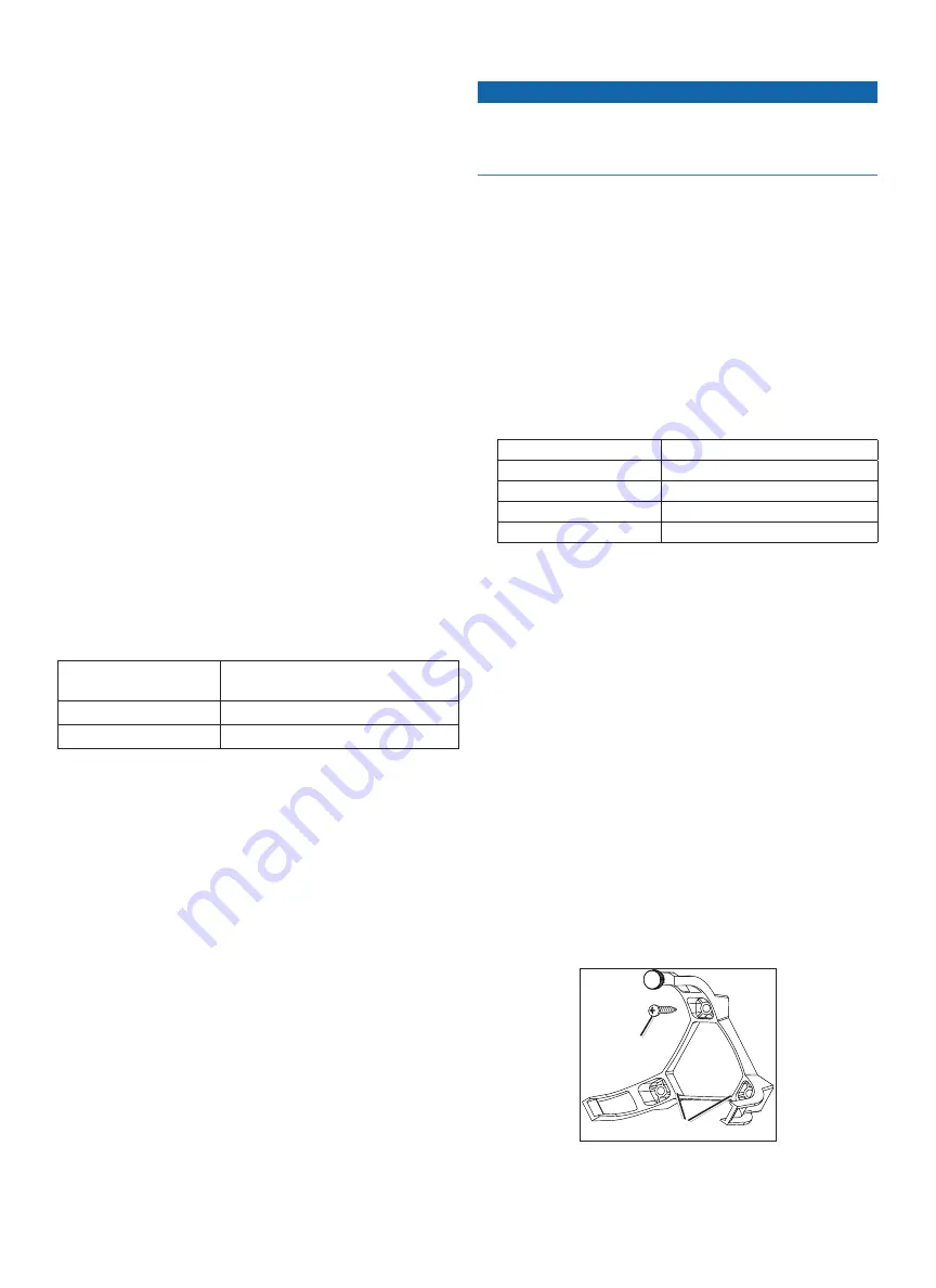
Installing the CCu Mounting Bracket

Before you can mount the CCU, you must select a location and 

determine the correct mounting hardware (

page 5

).

The CCU bracket has two portions, the mounting portion and the 

securing portion.
1.  Cut out the mounting template provided on 

page 23

2.  Tape the template to the mounting location. 
  If you are installing the CCU on a vertical surface, install the 

mounting portion of the bracket with an opening 

 at the bottom.

3.  Drill pilot holes at the three mounting locations. 
4.  Use screws 

 to secure the mounting portion of the CCU bracket. 

Summary of Contents for GHP 10 Marine Autopilot System

Page 1: ...armin com support or contact Garmin USA by phone at 913 397 8200 or 800 800 1020 In the UK contact Garmin Europe Ltd by phone at 0808 2380000 In Europe go to www garmin com support and click Contact S...

Page 2: ...nnecting the GHC 10 to an Existing NMEA 2000 Network 12 Connecting the CCU to an Existing NMEA 2000 Network 13 Building a Basic NMEA 2000 Network for the GHC 10 and the CCU 13 Connecting Optional Devi...

Page 3: ...e unit based on information from the CCU The ECU powers both the CCU and the drive unit Serial Number Hydraulic Pump and Motor The hydraulic pump and motor steers your boat by interacting with the hyd...

Page 4: ...and the GHC 10 to the NMEA 2000 network Either connect the CCU and the GHC 10 to an existing NMEA 2000 network using the included T connectors and drop cables or use all of the included NMEA 2000 cab...

Page 5: ...wash down ECU Connection Considerations The ECU power cable connects to the boat battery and it can be extended if needed page 10 ECU units with a serial number prior to 19E002748 are only compatible...

Page 6: ...er of best to least in terms of autopilot performance Speed Source Appropriate Connection NMEA 2000 Engine Data If your engine supports NMEA 2000 engine data and is connected to the same NMEA 2000 net...

Page 7: ...to a 9 16 Vdc power source NMEA 2000 network The GHC 10 and the CCU must be connected to the NMEA 2000 network using the included T connectors page 12 If there is not an existing NMEA 2000 network on...

Page 8: ...onnect cable and the black wire from the GHC 10 data cable must be connected to the same ground as the ECU page 12 CCU The CCU must be installed in the front half of the boat no higher than 10 ft 3 m...

Page 9: ...le and the black wire from the GHC 10 data cable must be connected to the same ground as the ECU page 12 CCU The CCU must be installed in the front half of the boat no higher than 10 ft 3 m above the...

Page 10: ...Cut out the mounting template provided on page 23 2 Tape the template to the mounting location 3 Drill pilot holes at the four mounting locations 4 Use screws to mount the ECU Connecting the ECU to Po...

Page 11: ...Installation The alarm audibly alerts you to important GHP 10 events To install the alarm you must mount it to your boat page 10 connect it to the CCU page 10 and connect it to the yellow CCU signal...

Page 12: ...be at software version 3 0 or later All additional GHC 10 devices must be connected to the NMEA 2000 network page 12 To use an additional GHC 10 to turn on the autopilot connect the yellow and black w...

Page 13: ...nect it to the T connector If the included drop cable is not long enough you can use a drop cable up to 20 ft 6 m long not included 6 Connect the drop cable to the to the CCU Building a Basic NMEA 200...

Page 14: ...while your boat is out of the water provide rudder movement clearance to avoid damage to the rudder or other objects You can complete the Dockside Wizard while your boat is in or out of the water If y...

Page 15: ...lete the wizard in conditions appropriate for your boat Important Sea Trial Wizard Considerations Complete the Sea Trial Wizard in calm water The nature of calm water is relative to the size and shape...

Page 16: ...ing Adjustment This procedure appears only if you do not have an optional GPS device connected to the GHP 10 page 14 If you do have a GPS device installed on your boat that has acquired a GPS position...

Page 17: ...takes control of the rudder 4 Use the arrows on the GHC 10 to adjust the speed of the limiter 0 is the is the default speed for the rudder rate limiter Lower rudder rate limiter numbers allow the rudd...

Page 18: ...Power N A NMEA 0183 ground Blue Tx A Rx White unconnected N A Brown Rx A Tx A Green Rx B Tx B NOTE When connecting a NMEA 0183 device with only one receiving Rx line the NMEA 2000 bus and the NMEA 018...

Page 19: ...Product Information 127258 Magnetic Variation 127488 Engine Parameters Rapid Update 129025 Position Rapid Update 129026 COG SOG Rapid Update 129283 Cross Track Error 129284 Navigation Data Transmit 0...

Page 20: ...ry Setting Description Speed Source Setup Low RPM Limit Allows you to adjust lowest RPM point of your boat If the value does not match the value on the GHC 10 use the arrows to adjust the value Speed...

Page 21: ...s too high the autopilot can oscillate back and forth across the course line over long distances If this value is too low the autopilot may respond slowly in eliminating cross track error Navigation S...

Page 22: ...supply voltage goes above a certain threshold 12v system 20 volts 24v system 36 volts Alarm sounds Drive unit is disabled GHC 10 begins a countdown timer that automatically powers off the autopilot a...

Page 23: ...GHP 10 Installation Instructions 23 ECU Mounting Template CCU Mounting Template Up when installing on a vertical surface...

Page 24: ......

Page 25: ...Connect the drive unit to the ECU Mount the CCU page 10 in a location free of magnetic interference Use a handheld compass to test for magnetic interference in the area Mount the CCU in the bracket s...

Page 26: ...Visit the Garmin Web site www garmin com for current updates and supplemental information concerning the use and operation of this and other Garmin products Garmin the Garmin logo and GPSMAP are regi...

Reviews: