background image

Garmin G1000 Pilot’s Guide for the Diamond DA62

190-01895-00  Rev. A

500

ADDITIONAL FEATURES

SY

STEM

O

VER

VIEW

FLIGHT

INSTRUMENTS

EIS

AUDIO P

ANEL

& CNS

FLIGHT

MANA

GEMENT

HAZARD

AV

OID

ANCE

AFCS

ADDITIONAL FEA

TURES

APPENDICES

INDEX

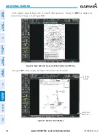
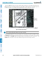
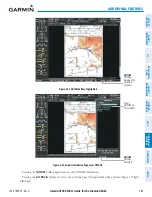
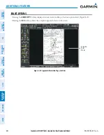
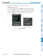
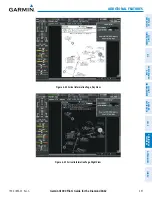
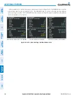
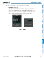
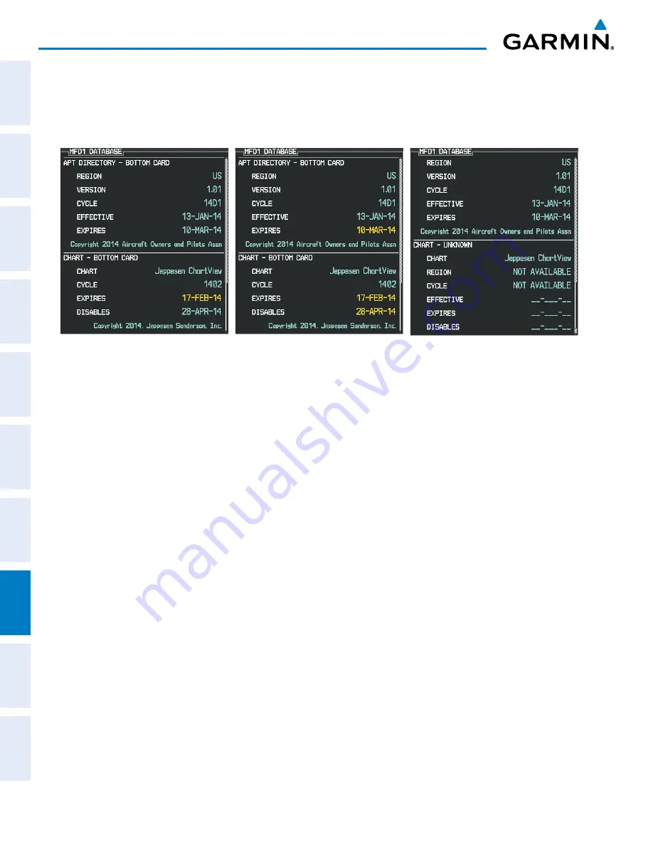
Other possible AUX - System Status page conditions are shown in Figure 8-48.  The EXPIRES date, in yellow, 

is the revision date for the next database cycle.  The DISABLES date, in yellow, is the date that this database 
cycle is no longer viewable.  NOT AVAILABLE in blue, indicates no ChartView data is available on the database 
card or no database card is inserted.

Figure 8-48  AUX – System Status Page, ChartView Database Status

ChartView Database is Disabled

ChartView has Expired, but is not Disabled

ChartView Database is Not Available

Summary of Contents for G1000 Diamond DA62

Page 1: ...Garmin AT Inc 2345 Turner Road SE Salem OR 97302 U S A p 503 391 3411 f 503 364 2138 Garmin Europe Ltd Liberty House Houndsdown Business Park Southampton Hampshire SO40 9LR U K p 44 0 23 8052 4000 f 4...

Page 2: ......

Page 3: ...SYSTEM OVERVIEW FLIGHT INSTRUMENTS EIS AUDIO PANEL CNS FLIGHT MANAGEMENT HAZARD AVOIDANCE AFCS ADDITIONAL FEATURES APPENDICES INDEX...

Page 4: ...f Penton Business Media Inc SiriusXM Weather and SiriusXM Satellite Radio are provided by SiriusXM Satellite Radio Inc AOPA Membership Publications Inc and its related organizations hereinafter collec...

Page 5: ...ude displayed by the G1000 PFD or other pressure altimeters in aircraft WARNING Do not use outdated database information Databases used in the G1000 system must be updated regularly in order to ensure...

Page 6: ...and the Airplane Flight Manual Thoroughly practice basic operation prior to actual use During flight operations carefully compare indications from the G1000 to all available navigation sources includ...

Page 7: ...pairs or modifications could void both the warranty and the pilot s authority to operate this device under FAA FCC regulations NOTE When using the on board Lightning Detection System there are several...

Page 8: ...min equipment is required for compliance with established FAA regulatory guidance but does not constitute authorization to fly any and all terminal procedures that may be presented by the system It is...

Page 9: ...00 Rev A Garmin G1000 Pilot s Guide for the Diamond DA62 v REVISION INFORMATION Record of Revision Part Number Revision Date Page Range Description 190 01895 00 A i I 6 Initial release with GDU SW Ver...

Page 10: ...73 Low Altitude Annunciation 73 Minimum Descent Altitude Decision Height Alerting 74 Radar Altimeter 75 2 4 Abnormal Operations 77 Abnormal GPS Conditions 77 Unusual Attitudes 78 SECTION 3 ENGINE IND...

Page 11: ...ht Plan Views 219 Closest Point of FPL 221 User Defined Holding Patterns 221 5 7 Vertical Navigation 226 Altitude Constraints 228 5 8 Procedures 232 Departures 233 Arrivals 236 Approaches 239 5 9 Trip...

Page 12: ...Lateral Modes 434 Roll Hold Mode ROL 435 Heading Select Mode HDG 436 Navigation Modes GPS VOR LOC BC 437 Approach Modes GPS VAPP LOC 439 7 5 Autopilot and Yaw Damper Operation 441 Flight Control 441...

Page 13: ...1 Flight Data Logging 554 8 12 Auxiliary Video Optional 556 Video Setup 557 Display Selection 557 Zoom Range 558 8 13 Abnormal Operation 559 SVT Troubleshooting 559 Reversionary Mode 559 Unusual Attit...

Page 14: ...Garmin G1000 Pilot s Guide for the Diamond DA62 190 01895 00 Rev A x TABLE OF CONTENTS Blank Page...

Page 15: ...light Display PFD GDU 1045 Multi Function Display MFD GMA 1347 Audio Panel with Integrated Marker Beacon Receiver GIA 63W Integrated Avionics Units IAU GDC 74A Air Data Computer ADC GEA 71 Engine Airf...

Page 16: ...h the primary IAU displays and AHRS using an ARINC 429 digital interface GEA 71 The Engine Airframe Unit receives and processes signals from the engine and airframe sensors This unit communicates with...

Page 17: ...PANEL CNS FLIGHT MANAGEMENT HAZARD AVOIDANCE AFCS ADDITIONAL FEATURES APPENDICES INDEX GRA 5500 The optional Radar Altimeter provides altitude above the ground AGL to the MFD through the GIA 63W using...

Page 18: ...irspeed Altitude Vertical Speed GRS 77 AHRS Attitude Rate of Turn Slip Skid GTX 33 33ES Transponder GEA 71 Engine Airframe Unit GSA 81 Roll Servo Autopilot Calculations optional GSA 81 Pitch Servo Aut...

Page 19: ...bscription based service Avidyne TAS600 Series Traffic Advisory System optional Honeywell KN 63 DME optional Avidyne TWX 670 Lightning Strike and Thunderstorm Detection optional Garmin GRA 5500 Radar...

Page 20: ...and MFD data card slots use Secure Digital SD cards and are located on the upper right side of the display bezels Each display bezel is equipped with two SD card slots SD cards are used for aviation d...

Page 21: ...up key annunciator lights also become momentarily illuminated on the Audio Panel and the display bezels On the PFD the AHRS begins to initialize and displays AHRS ALIGN Keep Wings Level The AHRS shoul...

Page 22: ...s a full color moving map with navigation information see the Flight Management Section while the left portion of the MFD is dedicated to the Engine Indication System EIS see the EIS Section Both disp...

Page 23: ...the failed PFD Flagged Invalid G1000 SYSTEM ANNUNCIATIONS When an LRU or an LRU function fails a large red X is typically displayed over the instrument experiencing failed data Figure 1 8 displays all...

Page 24: ...for all detected system LRUs Active LRUs are indicated by green check marks failed by red X s Failed LRUs should be noted and a service center or Garmin authorized dealer informed Viewing LRU informa...

Page 25: ...t information on all system databases is also displayed on this page Refer to the Appendices and Additional Features sections for more information about databases Viewing database information 1 Use th...

Page 26: ...ble Air Data Magnetometer Data unavailable available GPS Data Magnetometer Data Air Data Loss of GPS magnetometer or air data inputs is communicated to the pilot by message advisory alerts refer to Ap...

Page 27: ...mation collected by the specified receiver GPS1 for the 1 IAU or GPS2 for the 2 IAU may be viewed on the AUX GPS Status Page Viewing GPS receiver status information 1 Use the large FMS Knob on the MFD...

Page 28: ...enough satellite signals for navigation the receiver uses satellite orbital data collected continuously from the satellites and last known position to determine the satellites that should be in view...

Page 29: ...r protection limit on approaches there may be times when RAIM is not available The G1000 automatically monitors RAIM and warns with an alert message when it is not available If RAIM is not predicted t...

Page 30: ...h bar is hollow before the satellite may be used for navigation signal strength bar becomes solid Solid signal strength bar Receiver has collected the necessary data and the satellite signal can be us...

Page 31: ...PFD and MFD bezels and Audio Panel PFD and MFD controls and softkeys are discussed in this section See the Audio Panel and CNS Section for more information about Audio Panel and NAV COM controls AFCS...

Page 32: ...n course pointer directly to bearing of active waypoint station 7 COM Knob Turn to tune COM transceiver standby frequencies large knob for MHz small for kHz Press to toggle cyan tuning box between COM...

Page 33: ...ts the hundreds SOFTKEY FUNCTION The softkeys are located along the bottoms of the displays The softkeys shown depend on the softkey level or page being displayed The bezel keys below the softkeys can...

Page 34: ...plan WX LGND Displays icon and age on the Inset Map for the selected weather products optional TRAFFIC 2 Displays removes traffic information on Inset Map TRFC 1 Displays traffic on Inset Map TRFC 2...

Page 35: ...y DME Displays removes DME Information Window optional BRG1 Cycles the Bearing 1 Information Window through NAV1 Waypoint frequency identifier and DME information GPS Waypoint identifier and GPS dista...

Page 36: ...onder does not reply to any interrogations ON Selects Mode A Transponder replies to interrogations ALT Selects Mode C altitude reporting mode Transponder replies to identification and altitude interro...

Page 37: ...EATURES APPENDICES INDEX NRST Displays removes Nearest Airports Window ALERTS Displays removes Alerts Window HPA BACK ALERTS METERS IN Press the BACK Softkey to return to the top level softkeys Press...

Page 38: ...urn to the top level softkeys FUEL PROFILE TOPO optional NEXRAD TRAFFIC TERRAIN optional XM LTNG Press the BACK softkey to return to the top level softkeys AIRWY LO AIRWY HI AIRWY ON AIRWAYS optional...

Page 39: ...scope weather information on Inset Map optional NEXRAD Displays removes NEXRAD weather coverage on Navigation Map Page optional XM LTNG Displays removes XM lightning information on Navigation Map Page...

Page 40: ...ENT Key to select the desired option 4 Press the CLR Key or FMS Knob to remove the menu and cancel the operation Figure 1 21 Page Menu Examples No Options for NRST Window Options for FPL Window DATA E...

Page 41: ...ts of nearest waypoints NRST and recently entered waypoints RECENT b Turn the large FMS Knob to highlight the desired waypoint from the list and press the ENT Key Or a Turn the small FMS Knob to selec...

Page 42: ...edures Weather Information XM Procedure Loading the title of the page changes while the page icon remains the same Figure 1 22 Page Title and Page Group Icons MFD Page Group Active Page Title Page Gro...

Page 43: ...l XM Weather Data Link service optional Terrain SVS or Terrain Proximity Figure 1 23 Map Pages Waypoint Page Group WPT Airport Procedures Weather Information Pages Airport Information INFO 1 INFO 2 So...

Page 44: ...tup Pages System Setup 1 SETUP 1 Softkey System Setup 2 SETUP 2 Softkey XM Satellite Pages optional XM Radio RADIO Softkey XM Information INFO Softkey Satellite Phone Telephone TEL Softkey SMS SMS Sof...

Page 45: ...es Flight Plan Page Group FPL Active Flight Plan Flight Plan Catalog Stored Flight Plan NEW Softkey The Procedure Loading pages may be accessed at any time on the MFD by pressing the PROC Key A menu i...

Page 46: ...Alert see Flight Instruments Section Airspace alerts see Flight Management Section Arrival alerts see Flight Management Section Audio Alerts MFD Data Bar Fields see Flight Management Section CDI scali...

Page 47: ...isplayed in three formats local 12 hr local 24 hr or UTC Local time is set by adding subtracting an offset hours minutes to from UTC Figure 1 30 System Time Local 24 hr Format PFD Configuring the syst...

Page 48: ...Desired Track Wind direction Trip Planning Page Distance and Speed Metric Nautical Crosstrack error HSI Bearing distances information windows DME distance information window Flight plan distances Map...

Page 49: ...NCE AFCS ADDITIONAL FEATURES APPENDICES INDEX Category Settings Affected Quantities Exceptions Fuel and Fuel Flow Gallons Imp Gallons Kilograms Liters Pounds Fuel parameters Trip Planning Page Engine...

Page 50: ...be created selected renamed or deleted Figure 1 33 Pilot Profile Settings AUX System Setup Page Creating a profile 1 Use the FMS Knob to select the AUX System Setup Page 2 Press the FMS Knob momentar...

Page 51: ...system settings for the selected profile Renaming a profile 1 Use the FMS Knob to select the AUX System Setup Page 2 Press the FMS Knob momentarily to activate the flashing cursor 3 Turn the large FM...

Page 52: ...e reaching zero on a countdown the digits are reset to the initial value If the timer is counting up when reset the digits are zeroed Setting the generic timer PFD 1 Press the TMR REF Softkey 2 Turn t...

Page 53: ...he HH MM SS field b Use the FMS Knob to enter the desired time and press the ENT Key 5 Turn the large FMS Knob to highlight START and press the ENT Key to start the timer The field changes to STOP 6 T...

Page 54: ...ay the current time at the point of reset The format in which the time is displayed is controlled from the System Setup Page Setting the departure timer starting criterion 1 Use the FMS Knob to select...

Page 55: ...ts document NOTE Garmin is not responsible for the content of checklists Checklists are created by the aircraft manufacturer Modifications or updates to the checklists are coordinated through the airc...

Page 56: ...box for checkmark The following colors are used for checklist items Blue Items has not been highlighted White Item is highlighted for selection Green Item has been selected Yellow Warning notes 7 Pre...

Page 57: ...g 1 Press the PFD MENU Key to display the PFD Setup Menu AUTO is now highlighted next to PFD DSPL 2 Turn the small FMS Knob to select MANUAL 3 Press the ENT Key The intensity value is now highlighted...

Page 58: ...ilot s Guide for the Diamond DA62 190 01895 00 Rev A 44 SYSTEM OVERVIEW SYSTEM OVERVIEW FLIGHT INSTRUMENTS EIS AUDIO PANEL CNS FLIGHT MANAGEMENT HAZARD AVOIDANCE AFCS ADDITIONAL FEATURES APPENDICES IN...

Page 59: ...r sections of this Pilot s Guide The following flight instruments and supplemental flight data are displayed on the PFD Airspeed Indicator showing Indicated airspeed True airspeed Airspeed awareness r...

Page 60: ...Indicator 3 True Airspeed 4 Current Heading 5 Turn Rate Indicator 6 Horizontal Situation Indicator HSI 7 Outside Air Temperature OAT 8 Softkeys 9 System Time 10 Transponder Data Box 11 Heading Bug 12...

Page 61: ...FD Information 1 Traffic Annunciation 2 Selected Heading 3 Wind Data 4 Inset Map 5 DME Information Window optional 6 Bearing Information Windows 7 Barometric Minimum Descent Altitude Decision Height 8...

Page 62: ...ow Speed Range Speed Ranges Indicated Airspeed True Airspeed Airspeed Indicator Operating Ranges Airspeed Trend Vector VYSE VMCA Vspeed Bugs Flaps Operating Range Color coded stripes appear on the Air...

Page 63: ...highlight the field of the desired Vspeed to be changed 3 Use the FMS Knob to enter the desired value When a speed has been changed from a default value an asterisk appears next to the speed 4 Press...

Page 64: ...every 10 up to 80 Minor pitch marks are shown for intervening 5 increments up to 25 below and 45 above the horizon line Between 20 below to 20 above the horizon line minor pitch marks occur every 2 5...

Page 65: ...ower edge of the tape When the metric value is selected it is displayed in a separate box above the Selected Altitude A magenta Altitude Trend Vector extends up or down the left of the altitude tape t...

Page 66: ...ish on the descent patch If the change is made while nearing a waypoint with a VNV Target Altitude the aircraft may not re establish on the descent path in time to meet the vertical constraint WARNING...

Page 67: ...changed from STD BARO the setting flashes in cyan until it is changed Figure 2 10 Setting the Baro Transition Alert 1 Use the FMS Knob to select the AUX System Setup Page on the MFD 2 Press the FMS Kn...

Page 68: ...Indicator appears to the left of the Altimeter whenever an ILS frequency is tuned in the active NAV field A green diamond acts as the Glideslope Indicator like a glideslope needle on a conventional in...

Page 69: ...rmats a 360 compass rose and a 140 arc Changing the HSI display format 1 Press the PFD Softkey 2 Press the HSI FRMT Softkey 3 Press the 360 HSI or ARC HSI Softkey The 360 HSI contains a Course Deviati...

Page 70: ...ck Indicator The selected heading is shown to the upper left of the HSI for 3 seconds after being adjusted The cyan heading bug on the compass rose corresponds to the selected heading While the HSI is...

Page 71: ...the flight plan the system generates a message to change the navigation angle setting to True at the appropriate time Figure 2 17 Heading and Course Indications True Changing the navigation angle true...

Page 72: ...magenta trend vector and the prediction is no longer valid Arrow Shown for Turn Rate 4 deg sec Half standard Turn Rate Standard Turn Rate Figure 2 19 Turn Rate Indicator and Trend Vector BEARING POIN...

Page 73: ...HSI and NO DATA is displayed in the information window if the NAV radio is not receiving a VOR station or if GPS is the bearing source and an active waypoint is not selected Selecting bearing display...

Page 74: ...e to the course If the course deviation data is not valid the CDI is not displayed Figure 2 21 Course Deviation Indicator Navigation Source Scale CDI Crosstrack Error 360 HSI Flight Phase CDI Navigati...

Page 75: ...2 23 Selecting a Navigation Source LOC1 Selected NAV1 Selected for Tuning VOR2 Selected NAV2 Selected for Tuning ThesystemautomaticallyswitchesfromGPStoLOCnavigationsourceandchangestheCDIscalingaccor...

Page 76: ...e flight phase Flight phase annunciations are normally shown in magenta but when cautionary conditions exist the color changes to yellow If the current leg in the flight plan is a heading leg HDG LEG...

Page 77: ...Terminal 1 0 nm Terminal 0 3 nm Departure CDI Full scale Deflection Refer to accompanying approach CDI scaling figures Once a departure procedure is activated the CDI is scaled for departure 0 3 nm T...

Page 78: ...ithin 2 0 nm of the final approach fix FAF The CDI switches to approach scaling automatically once the approach procedure is activated or if Vectors To Final VTF are selected If the active waypoint is...

Page 79: ...tions are normally shown in magenta but when cautionary conditions exist the color changes to yellow Table 2 1 Automatic GPS CDI Scaling OBS MODE NOTE VNV is inhibited while automatic waypoint sequenc...

Page 80: ...t OBS Mode 2 Turn the CRS Knob to select the desired course to from the waypoint Press the CRS Knob to synchronize the Selected Course with the bearing to the next waypoint 3 Press the OBS Softkey aga...

Page 81: ...t Map and wind data display In addition to the flight instruments the PFD also displays various supplemental information including temperatures wind data and Vertical Navigation VNV indications OUTSID...

Page 82: ...ture display units 1 Select the AUX System Setup Page on the MFD using the FMS Knob 2 Press the FMS Knob to activate the cursor 3 Turn the large FMS Knob to highlight the TEMP field in the Display Uni...

Page 83: ...r unavailable the window displays NO WIND DATA Wind data can be displayed in three different ways Figure 2 33 Wind Data No Data Option 2 Option 1 Option 3 Displaying wind data 1 Press the PFD Softkey...

Page 84: ...de GPS is the Selected Navigation Source Phase of Flight Required Vertical Speed Indicator Figure 2 34 Vertical Navigation Indications PFD Vertical Deviation Indicator Top of Descent Message Criteria...

Page 85: ...Alerts Window is enabled disabled by pressing the ALERTS Softkey If the window is already open when a new message is generated pressing the ALERTS Softkey to acknowledge the message turns the softkey...

Page 86: ...he PFD Inset Map the MFD Navigation Map Page and various other MFD page maps Refer to the Hazard Avoidance Section and Appendix for more details about the Traffic Information Service TIS and optional...

Page 87: ...flashes for five seconds After reaching the Selected Altitude if the pilot flies outside the deviation band 200 feet of the Selected Altitude an aural tone is heard The Selected Altitude changes to y...

Page 88: ...n once in range When the aircraft passes through 100 feet of the MDA DH the bug and text turn white Once the aircraft reaches MDA DH the bug and text turn yellow and the aural alert Minimums Minimums...

Page 89: ...e right of the current aircraft heading Figure 2 42 Display of radar height becomes more sensitive as the height above ground decreases Table 2 3 Figure 2 42 Current Radar Height Radar Altimeter Radar...

Page 90: ...ound line Figure 2 45 appears on the Altimeter to display the aircraft s height relative to the ground Diagonal lines appear underneath the ground line If the radar altimeter provides invalid data the...

Page 91: ...nnunciation displayed for 5 seconds DR Upper right of aircraft symbol DeadReckoning SystemisusingprojectedpositionratherthanGPSposition to compute navigation data and sequence active flight plan waypo...

Page 92: ...ntal Situation indicators remain on the display and the Bearing Information Alerts and Annunciation windows can be displayed during such situations The following information is removed from the PFD an...

Page 93: ...ows graphic and numeric readouts of critical engine electrical indicators and optional deice fluid quantity Fuel Display Shows numeric readouts of fuel indicators and calculations and total aircraft t...

Page 94: ...APPENDICES INDEX In Reversionary Display mode the operating display is configured to present PFD symbology with the EIS Display Figure 3 2 When a G1000 display enters Reversionary Mode each EIS Displ...

Page 95: ...splay press the ENGINE or BACK Softkey ENGINE Press the BACK Softkey to return to the top level softkeys FUEL ENGINE SYSTEM INC FUEL RST FUEL DEC FUEL BACK FUEL ENGINE SYSTEM BACK ALERTS ALERTS Figure...

Page 96: ...douts below the gauge 2 Tachometer RPM Displays propeller speeds in revolutions per minute rpm on a vertical slider gauge with digital readouts below the gauge Gauge indicators display propeller speed...

Page 97: ...lot s Guide for the Diamond DA62 83 ENGINE INDICATION SYSTEM SYSTEM OVERVIEW FLIGHT INSTRUMENTS EIS AUDIO PANEL CNS FLIGHT MANAGEMENT HAZARD AVOIDANCE AFCS ADDITIONAL FEATURES APPENDICES INDEX Figure...

Page 98: ...isplays current engine loads as percentages on a vertical bar gauge with digital readouts below the gauge 2 Tachometer RPM Displays propeller speeds in revolutions per minute rpm on a vertical slider...

Page 99: ...ot s Guide for the Diamond DA62 85 ENGINE INDICATION SYSTEM SYSTEM OVERVIEW FLIGHT INSTRUMENTS EIS AUDIO PANEL CNS FLIGHT MANAGEMENT HAZARD AVOIDANCE AFCS ADDITIONAL FEATURES APPENDICES INDEX Figure 3...

Page 100: ...percentages on a vertical bar gauge with digital readouts below the gauge 2 Tachometer RPM Displays propeller speeds in revolutions per minute rpm on a vertical slider gauge with digital readouts belo...

Page 101: ...UEL Increases totalizer based fuel remaining in one gallon increments RST FUEL Resets totalizer based fuel remaining GAL REM relative to the aircraft s fuel capacity and sets the displayed fuel used G...

Page 102: ...s Guide for the Diamond DA62 190 01895 00 Rev A 88 ENGINE INDICATION SYSTEM SYSTEM OVERVIEW FLIGHT INSTRUMENTS EIS AUDIO PANEL CNS FLIGHT MANAGEMENT HAZARD AVOIDANCE AFCS ADDITIONAL FEATURES APPENDICE...

Page 103: ...Integrated Avionics Unit 2 Audio Panel Mode S Transponder The MFD PFD controls are used to tune the communication transceivers and navigation radios The Audio Panel provides the traditional audio sel...

Page 104: ...YSTEM OVERVIEW FLIGHT INSTRUMENTS EIS AUDIO PANEL CNS FLIGHT MANAGEMENT HAZARD AVOIDANCE AFCS ADDITIONAL FEATURES APPENDICES INDEX MFD PFD CONTROLS AND FREQUENCY DISPLAY Figure 4 1 MFD PFD Controls NA...

Page 105: ...er large knob for MHz small knob for kHz Press to move the tuning box cyan box and Frequency Transfer Arrow between COM1 and COM2 7 COM Frequency Transfer Key Transfers the standby and active COM freq...

Page 106: ...COM1 MIC Selects the 1 transmitter for transmitting COM1 receive is simultaneously selected when this key is pressed allowing received audio from the 1 COM receiver to be heard COM2 receive can be add...

Page 107: ...an be heard 15 ADF Turns optional ADF receiver audio on or off 16 NAV2 When selected audio from the 2 NAV receiver can be heard 17 AUX Not used in DA62 aircraft 18 MAN SQ Enables manual squelch for th...

Page 108: ...t side and the two standby frequencies are on the right The COM transceiver is selected for transmitting by pressing the COM MIC Keys on the Audio Panel During reception of audio from the COM radio se...

Page 109: ...section and details on the Data Link Receiver in the Additional Features Section Figure 4 4 COM Radio Transmit and Receive Indications Annunciator Flashes During Transmission Transmit and Receive Indi...

Page 110: ...lower radio frequency fields Figure 4 6 Switching COM Tuning Boxes Press the COM Knob to Switch the Tuning Box From One COM Radio to the Other QUICK TUNING AND ACTIVATING 121 500 MHZ Pressing and hol...

Page 111: ...the Nearest Airports Window on the PFD When the desired frequency is entered it becomes a standby frequency Pressing the Frequency Transfer Key places this frequency into the COM Active Frequency Fiel...

Page 112: ...he ENT Key to load the COM frequency into the standby field of the selected COM radio 4 Press the Frequency Transfer Key to transfer the frequency to the COM Active Frequency Field Figure 4 9 Frequenc...

Page 113: ...e frequency field by pressing the FMS Knob and scrolling through the list The frequency is transferred to the COM Standby Field with the ENT Key Figure 4 11 WPT Airport Information Page Press ENT Key...

Page 114: ...OIDANCE AFCS ADDITIONAL FEATURES APPENDICES INDEX COM frequencies can also be auto tuned from the NRST Nearest Airspaces NRST Nearest Frequencies and NRST Nearest Airports Pages on the MFD in a simila...

Page 115: ...the complete 3040 channel list COM channel spacing is set on the System Setup Page of the AUX Page Group Figure 4 13 COM Channel Spacing 25 kHz Channel Spacing 8 33 kHz Channel Spacing Changing COM fr...

Page 116: ...tion is always on Continuous static noise is heard over the headsets and speaker if selected Pressing the VOL SQ Knob again enables Automatic Squelch Press the COM VOL SQ Knob to turn off Automatic Sq...

Page 117: ...While cycling through the CDI Softkey selections the NAV Tuning Box and the Frequency Transfer Arrow are placed in the active NAV Frequency Field and the active NAV frequency color changes to green Th...

Page 118: ...Selecting a NAV Radio Receiver NAV RECEIVER MANUAL TUNING The NAV frequency controls and frequency boxes are on the left side of the MFD and PFD Manually tuning a NAV frequency 1 Turn the NAV Knob to...

Page 119: ...ple shown in order to listen to either station identifier press the NAV1 or NAV2 Key on the Audio Panel Pressing the VOL ID Knob turns off the Morse code audio only in the radio with the NAV Tuning Bo...

Page 120: ...equencies can be automatically loaded into the NAV Frequency Box from pages in the NRST or WPT page group by highlighting the frequency and pressing the ENT Key Figures 4 23 4 24 and 4 25 Auto tuning...

Page 121: ...the large FMS Knob to scroll through the menu options 3 Press the ENT Key to place the cursor in the desired window 4 Scroll through the frequency selections with the FMS Knob or the ENT Key 5 Press...

Page 122: ...the VOR Softkey or from the page menu The FMS Knob or ENT Key is used to scroll through the list The cursor is placed on the frequency with the FREQ Softkey and loaded into the NAV Tuning Box with th...

Page 123: ...URES APPENDICES INDEX While enroute NAV frequencies can also be auto tuned from the NRST Nearest Airports WPT Airport Information WPT VOR Information and NRST Nearest Frequencies Pages on the MFD in a...

Page 124: ...details NAV frequencies are automatically loaded into the NAV Frequency Box on approach activation When loading or activating a VOR or ILS LOC approach the approach frequency is automatically transfe...

Page 125: ...Key selects and deselects marker beacon audio The key annunciator indicates when marker beacon audio is selected Pressing the MKR MUTE Key mutes the audio but does not affect the marker annunciations...

Page 126: ...r DME depending on installed equipment The UHF DME frequency is tuned by pairing with a VHF NAV frequency DME frequency pairing is automatic and only the VHF NAV frequency is shown The following ADF D...

Page 127: ...FMS Knob to move the cursor to the next digit position 5 Press the ENT Key to complete data entry for the standby frequency Figure 4 30 Entering ADF Standby Frequencies Press the ENT Key to Complete...

Page 128: ...ons used in various parts of the world ANT BFO Antenna Beat Frequency Oscillator The ADF bearing pointer parks on the HSI at 90 degrees while an audible tone is provided when a signal is received This...

Page 129: ...odes The following DME transceiver pairing can be selected NAV1 Pairs the DME frequency from the selected NAV1 frequency NAV2 Pairs the DME frequency from the selected NAV2 frequency HOLD When in the...

Page 130: ...er the extended squitter is transmitted periodically and contains information such as altitude barometric and GPS GPS position and aircraft identification The purpose of extended squitter is to provid...

Page 131: ...d by pressing the XPDR Softkey Selecting a transponder mode 1 Press the XPDR Softkey to display the Transponder Mode Selection Softkeys 2 Press the desired softkey to activate the transponder mode GRO...

Page 132: ...tered When Standby is selected a white STBY indication and transponder code appear in the mode field of the Transponder Data Box In all other modes these fields appear in green STBY Mode White Code Nu...

Page 133: ...A Mode C and Mode S replies as well as transmissions of acquisition and extended squitters including ADS B out if equipped If Altitude Mode is selected a green ALT indication and transponder code app...

Page 134: ...Softkey to display the Transponder Code Selection Softkeys for digit entry 3 Press the digit softkeys to enter the code in the code field When entering the code the next softkey in sequence must be pr...

Page 135: ...TRUMENTS EIS AUDIO PANEL CNS FLIGHT MANAGEMENT HAZARD AVOIDANCE AFCS ADDITIONAL FEATURES APPENDICES INDEX Figure 4 42 Entering a Code with the FMS Knob Press the ENT Key to Complete Code Entry Turn th...

Page 136: ...nge is required contact a Garmin authorized service center for configuration Figure 4 43 VFR Code VFR Code IDENT FUNCTION NOTE In Standby Mode the IDENT Softkey is inoperative Pressing the IDENT Softk...

Page 137: ...he system automatically removes it upon completion of Flight ID entry Entering a Flight ID 1 Press the TMR REF Softkey to display the Timer References Window 2 Press the FMS Knob to activate the selec...

Page 138: ...ears only the left channel in both ears If a monaural headset is used at one of the passenger positions any other passenger using a stereo headset hears audio in the left ear only INTERCOM The Audio P...

Page 139: ...icate with everyone else INTERCOM VOLUME AND SQUELCH The PILOT PASS Knob controls volume or manual squelch adjustment for the pilot and copilot passenger The small knob controls the pilot volume and s...

Page 140: ...est block The PLAY Key controls the play function Pressing the PLAY Key once plays the latest recorded memory block The PLAY Annunciator flashes to indicate when play is in progress The PLAY Annunciat...

Page 141: ...ey selects Split COM operation The COM 1 2 Annunciator is illuminated indicating Split COM operation COM1 and COM2 frequencies are displayed in green indicating that both transceivers are active Split...

Page 142: ...e G1000 System the following steps aid in maximizing the use of the Audio Panel as well as preventing pilot and copilot induced issues These preflight procedures should be performed each time a pilot...

Page 143: ...COM2 MIC Key Annunciator on the Audio Panel flashes as long as the PTT Key remains stuck Figure 4 51 Stuck Microphone Alert COM TUNING FAILURE In case of a COM system tuning failure the emergency fre...

Page 144: ...A Garmin G1000 Pilot s Guide for the Diamond DA62 130 AUDIO PANEL AND CNS SYSTEM OVERVIEW FLIGHT INSTRUMENTS EIS AUDIO PANEL CNS FLIGHT MANAGEMENT HAZARD AVOIDANCE AFCS ADDITIONAL FEATURES APPENDICES...

Page 145: ...NSET Softkey Selecting the INSET Softkey again then selecting the OFF Softkey removes the Inset Map The Navigation Map displays aviation data e g airports VORs airways airspaces geographic data e g ci...

Page 146: ...res Window Nearest Airports Window Inset Map Navigation Status Box Navigation Mode Figure 5 2 GPS Navigation Information on the MFD Navigation Page Active Flight Plan Leg Navigation Map Aviation Data...

Page 147: ...ISA Relative Temperature DTK Desired Track LDG ETA at Final Destination END Endurance MSA Minimum Safe Altitude ENR ETE to Final Destination TAS True Air Speed ESA Enroute Safe Altitude TKE Track Angl...

Page 148: ...ange ring Obstacle data Fuel range ring The information in this section applies to the following maps unless otherwise noted All Map Group Pages MAP Flight Plan Pages FPL All Waypoint Group Pages WPT...

Page 149: ...ion data reflect the orientation selected for the Navigation Map Page Changing the Navigation Map orientation 1 With the Navigation Map Page displayed press the MENU Key The cursor flashes on the Map...

Page 150: ...avigation Map Page MAP RANGE There are 28 different map ranges available from 500 feet to 2000 nm The current range is indicated in the lower right corner of the map and represents the top to bottom d...

Page 151: ...ap range to decrease to a point where situational awareness may not be what is desired Increase the minimum look ahead time to a value that limits the auto zoom to a minimum range that provides accept...

Page 152: ...he FMS Knob to return to the Navigation Map Page MAP PANNING Map panning allows the pilot to View parts of the map outside the displayed range without adjusting the map range Highlight and select loca...

Page 153: ...ed and there has been no pointer movement for about 60 seconds the map reverts back to centered on the aircraft position and the flashing pointer is removed When the Map Pointer is placed on an object...

Page 154: ...pace information is shown at the top of the display The information includes the name and class of airspace the ceiling in feet above Mean Sea Level MSL and the floor in feet MSL Figure 5 10 Navigatio...

Page 155: ...ewing information for an airport NAVAID or user waypoint 1 Place the Map Pointer on a waypoint 2 Press the ENT Key to display the Waypoint Information Page for the selected waypoint 3 Press the GO BAC...

Page 156: ...a special use or controlled airspace 1 Place the Map Pointer on an open area within the boundaries of an airspace 2 Press the ENT Key to display an options menu 3 Review Airspaces should already be h...

Page 157: ...the Measure Pointer is provided in a window at the top of the navigation map Measuring bearing and distance between any two points 1 Press the MENU Key with the Navigation Map Page displayed 2 Highli...

Page 158: ...the MENU Key 2 Select Show Profile View or Hide Profile View and press the ENT Key Navigation Map Black Background TOPO Off Figure 5 14 Navigation Map Topographic Data TOPO Softkey Enabled Navigation...

Page 159: ...e g a setting of 100 nm removes the item at ranges above 100 nm on MFD navigation maps while the PFD Inset Map removes the same item at 50 nm Selecting a topographical data range TOPO DATA 1 Press th...

Page 160: ...Elevation at Map Pointer Location only visible when Map Pointer is displayed Range of Displayed Elevations Displaying removing the topographic scale TOPO SCALE 1 Press the MENU Key with the Navigation...

Page 161: ...ing the DCLTR Softkey is also discussed LAND SYMBOLS The following items are configured on the land menu Land Symbols Text label size can be None Small Medium Med or Large Lrg Symbol Default Range nm...

Page 162: ...NAVAIDs 2000 2000 Large Airports LARGE APT Longest Runway 8100 ft 250 500 Medium Airports MEDIUM APT 8100 ft Longest Runway 5000 ft 150 300 Small Airports SMALL APT Longest Runway 5000 ft Medium Airpo...

Page 163: ...shes on the Map option 3 Highlight the LAND DATA field 4 Select On or Off 5 Press the FMS Knob to return to the Navigation Map Page Figure 5 18 Navigation Map Setup Menu LAND DATA Setup LAND DATA On O...

Page 164: ...gure 5 19 Navigation Map Setup Menu LAND GROUP Setup Maximum Display Range Text Label Size None Small Med or Lrg Figure 5 20 Navigation Map Setup Menu AVIATION GROUP Setup Maximum Display Range Text L...

Page 165: ...ion Figure 5 21 Navigation Map Declutter Level Indications Declutter Level Navigation Map Page Menu DCLTR Softkey Decluttering the map Select the DCLTR Softkey with the Navigation Map Page displayed T...

Page 166: ...ter 2 Declutter 3 Data Link Radar Precipitation X Data Link Lightning X Graphical METARs X Airports X Safe Taxi X Runway Labels X TFRs X Restricted X MOA Military X User Waypoints X X Latitude Longitu...

Page 167: ...ated with a V before the airway number hence the name Victor Airways since they run primarily between VORs High Altitude Airways or Jet Routes primarily serve airliners jets turboprops and turbocharge...

Page 168: ...displayed The cursor flashes on the Map Setup option 2 Press the ENT Key The Map Setup Menu is displayed 3 Turn the small FMS Knob to select the Airways group and press the ENT Key 4 Turn the large F...

Page 169: ...o a predicted location The track vector look ahead time is selectable 30 sec 60 sec default 2 min 5 min 10 min 20 min and determines the length of the track vector The track vector shows up to 90 degr...

Page 170: ...w in the upper right hand portion of the screen Wind vector information is displayed as a white arrow pointing in the direction in which the wind is moving for wind speeds greater than or equal to 1 k...

Page 171: ...vigation Map Nav Range Ring Nav Range Ring Range radius NOTE The Nav Range Ring is not displayed on the Waypoint Information pages Nearest pages or Direct to Window map Displaying removing the Nav Ran...

Page 172: ...n Map Fuel Range Ring Range to Reserve Fuel Time to Reserve Fuel Total Endurance Range Displaying removing the fuel range ring and selecting a fuel range time 1 Press the MENU Key with the Navigation...

Page 173: ...ashed lines forming a V shape in front of the aircraft symbol on the map This is only available if SVT is installed on the aircraft Figure 5 29 Navigation Map Field of View Lateral Field of View Bound...

Page 174: ...selected altitude The location will be shown as a cyan arc when the aircraft is actuallly climbing or descending Figure 5 30 Navigation Map Range to Altitude Arc Range to Altitude Arc Displaying remov...

Page 175: ...e facility or by entering the city name See the System Overview section for detailed instructions on entering data in the G1000 As a waypoint identifier facility name or location is entered the G1000...

Page 176: ...quencies COM NAV and lighting review runways and review instrument procedures that may be involved in the flight plan See the Audio Panel and CNS Section for more information on loading frequencies au...

Page 177: ...rport Information ID Facility City Usage Type Region Lat Long Elev Fuel Available Time Zone UTC Offset COM NAV Freq Info Identification Frequency Availability Additional Information Softkeys The follo...

Page 178: ...s TPA Aircraft Class Altitude Runway Headings Length Width Obstructions Surface Phones Phone Fax Numbers Weather Service Type Frequency Phone Number Obstructions GeneralAirport Obstructions Hours Faci...

Page 179: ...The Destination Airport is displayed The Airport Frequencies Box uses the descriptions and abbreviations listed in the following table Communication Frequencies Navigation Frequencies Approach Arriva...

Page 180: ...ormation pages for all airports in the Nearest Airports list Figure 5 36 Airport Information Window on PFD Airport Information Usage Time Elev Region Airport Information Lat Long Airport Information I...

Page 181: ...Knob and press the ENT Key to display the Airport Information Window 3 To return to the Nearest Airports Window press the ENT Key with the cursor on BACK or press the CLR Key The cursor is now on the...

Page 182: ...ways or runways that are not appropriately surfaced from being displayed Default settings are 0 feet or meters for runway length and HARD SOFT for runway surface type Selecting nearest airport surface...

Page 183: ...formation Page displays intersection information in three boxes labeled INTERSECTION INFORMATION and NEAREST VOR Figure 5 39 Intersection Information Page Selected Intersection Navigation Map Showing...

Page 184: ...labeled NEAREST INT INFORMATION and REFERENCE VOR The selected intersection is indicated by a white arrow Up to eleven intersections are visible at a time If there are more than can be shown the list...

Page 185: ...est City Nearest Airport Info Identifier Type symbol Bearing Distance to Airport NDB Information Type Region Lat Long NDB Frequency NOTE Compass locator LOM LMM a low power low or medium frequency rad...

Page 186: ...NDB INFORMATION and FREQUENCY A white arrow before the NDB identifier indicates the selected NDB Up to eleven NDBs are visible at a time If there are more than can be shown each list can be scrolled T...

Page 187: ...R Information Page displays VOR information in four boxes labeled VOR INFORMATION FREQUENCY and NEAREST AIRPORT Figure 5 43 VOR Information Page Selected VOR Navigation Map Showing Selected VOR VOR Id...

Page 188: ...he Nearest VOR Page In addition to displaying a map of the surrounding area the Nearest VOR Page displays information for up to 25 nearest VOR stations in three boxes labeled NEAREST VOR INFORMATION a...

Page 189: ...waypoints are erased upon system power down Figure 5 45 User Waypoint Information Page Selected User Waypoint Navigation Map Showing Selected User Waypoint User Waypoint List Identifier Comment Softk...

Page 190: ...o six characters 3 Press the ENT Key The current aircraft position is the default location of the new waypoint 4 If desired define the type and location of the waypoint in one of the following ways a...

Page 191: ...using the FMS Knobs Or c Select LAT LON using the small FMS Knob press the ENT Key and enter the latitude and longitude into the INFORMATION window using the FMS Knobs 6 Press the ENT Key to accept t...

Page 192: ...N window using the FMS Knobs 6 Press the ENT Key to accept the new waypoint 7 If desired change the storage method of the waypoint to TEMPORARY or NORMAL by moving the cursor to TEMPORARY and selectin...

Page 193: ...ed comment has been edited a new comment can be generated Resetting the comment field to the system generated comment 1 Enter a waypoint name or select the waypoint in the User Waypoint List then pres...

Page 194: ...ndow 3 Press the ENT Key 4 Press the FMS Knob to remove the flashing cursor Or 1 Highlight a User Waypoint in the User Waypoint List or enter a waypoint in the User Waypoint field 2 Press the MENU Key...

Page 195: ...Airspaces MOA Military Class D Airspace Class B Airspace Restricted Area Class C Airspace Alert Area ADIZ Warning Area The Nearest Airspaces Page Airspace Alerts Window and Airspace Alerts on the PFD...

Page 196: ...he flashing cursor 3 Turn the large FMS Knob to highlight the altitude buffer field in the Airspace Alerts Box 4 Use the FMS Knob to enter an altitude buffer value and press the ENT Key 5 Press the FM...

Page 197: ...me Proximity Ahead Inside Ahead 2nm Within 2nm Time till Intercept only if Ahead or Ahead 2nm Airspace Vertical Limits Ceiling Floor Airspace Agency Info Airspace Type Controlling Agency Softkeys Airs...

Page 198: ...ace alerts are displayed in the message window Message Comments INSIDE ARSPC Inside airspace The aircraft is inside the airspace ARSPC AHEAD Airspace ahead less than 10 minutes Special use airspace is...

Page 199: ...vertical navigation VNV direct to creates a descent path and provides guidance to stay on the path from the current altitude to a selected altitude at the direct to waypoint Vertical navigation is ba...

Page 200: ...the ENT Key The Activate field is highlighted 4 Press the ENT Key to activate the direct to Any waypoint contained in the active flight plan can be selected as a direct to waypoint from the Direct to...

Page 201: ...he active flight plan waypoint if a flight plan is active or a blank waypoint field Direct to requests on any WPT page defaults to the displayed waypoint Selecting any waypoint as a direct to destinat...

Page 202: ...the closest leg Figure 5 54 Direct to Window Cancelling Direct to Navigation Page Menu Cancel Direct To Navigation When navigating a direct to the G1000 sets a direct great circle course to the select...

Page 203: ...See the section on Vertical Navigation for more information regarding the use and purpose of VNV altitudes and offset distances Entering a VNV altitude and along track offset for the waypoint 1 Press...

Page 204: ...t TOPO On Non heading Leg not in the current flight segment TOPO Off Turn Anticipation Arc TOPO On TOPO Off Table 5 7 Flight Plan Leg Symbols Up to 99 flight plans with up to 99 waypoints each can be...

Page 205: ...exit waypoint not found in the new database Airway entry exit waypoint is not an acceptable waypoint for the airway either the waypoint is no longer on the airway or there is a new directional restric...

Page 206: ...PL Info Departure Waypoint Destination Waypoint Total Flight Plan Distance Enroute Safe Altitude Catalog Contents Used Empty Softkeys Selected Flight Plan Map The active flight plan is listed on the a...

Page 207: ...r each additional flight plan waypoint 6 When all waypoints have been entered press the FMS Knob to remove the cursor Creating a stored flight plan 1 Press the FPL Key 2 Turn the small FMS Knob clockw...

Page 208: ...ss the IMPORT Softkey or press the MENU Key select Import Flight Plan and press the ENT Key If an empty slot is selected a list of the available flight plans on the SD card will be displayed Or If an...

Page 209: ...he top card slot on the MFD 2 Press the FPL Key to display the Active Flight Plan Page on the MFD 3 Turn the small FMS Knob to select the Flight Plan Catalog Page 4 Press the FMS Knob to activate the...

Page 210: ...and it is added in front of the selected waypoint Flight plans are limited to 99 waypoints including waypoints within airways and procedures If the number of waypoints in the flight plan exceeds 99 th...

Page 211: ...ts 6 Enter the identifier facility or city name of the waypoint or select a waypoint from the submenu of waypoints and press the ENT Key The new waypoint now exists in the flight plan NOTE If the iden...

Page 212: ...the airway and it is added in front of the selected waypoint An airway can only be loaded if there is a waypoint in the flight plan that is part of the desired airway and is not part of an arrival or...

Page 213: ...ys and then high altitude airways 6 Turn the FMS Knob to select the desired airway exit point from the list and press the ENT Key LOAD is highlighted 7 Press the ENT Key The system returns to editing...

Page 214: ...y to LIBRO Between NELDA and GZO the airway can be flown in either direction In the US airways that are one way for specified hours of operation are not uncommon These airways are always bidirectional...

Page 215: ...lected Departure Departures Available at KMKC Departure Waypoint Sequence Preview of Selected Departure Loading a departure procedure into a stored flight plan 1 Select a stored flight plan from the F...

Page 216: ...ure 5 69 Departure Loading Page Selecting Transition Departure Airport Selected Departure Departure Transition Points Available Selected Runway Selected Departure End Point Preview of Selected Departu...

Page 217: ...Selected Arrival Arrivals Available at KCOS Arrival Waypoint Sequence Preview of Selected Arrival Selected Runway Loading an arrival procedure into a stored flight plan 1 Select a stored flight plan...

Page 218: ...RES APPENDICES INDEX Figure 5 72 Arrival Loading Page Selecting the Transition Destination Airport Selected Arrival Transitions Available with DBRY1 Arrival Waypoint Sequence Preview of Selected Arriv...

Page 219: ...ght plan 1 Select a stored flight plan from the Flight Plan Catalog Page 2 Press the EDIT Softkey or press the MENU Key select Edit Flight Plan and press the ENT Key The Stored Flight Plan Page is dis...

Page 220: ...X Figure 5 75 Approach Loading Page Selecting the Transition Destination Airport Selected Approach Transitions Available with Selected Approach Approach Waypoint Sequence Preview of Selected Approach...

Page 221: ...the cursor and turn the FMS Knob to highlight the desired flight plan 4 The Flight Plan Information is displayed showing departure destination total distance and enroute safe altitude information for...

Page 222: ...light plan on the MFD 1 Press the FPL Key and turn the small FMS Knob to display the Flight Plan Catalog Page 2 Press the FMS Knob to activate the cursor and turn the FMS Knob to highlight the desired...

Page 223: ...hlight Delete All and press the ENT Key A Delete all flight plans confirmation window is displayed 4 With OK highlighted press the ENT Key to delete all flight plans To cancel the request press the CL...

Page 224: ...CLR Key or highlight CANCEL and press the ENT Key 5 Press the FMS Knob to remove the flashing cursor Deleting an entire procedure from the active flight plan 1 Press the FPL Key to display the Active...

Page 225: ...ght the white header of the airway to be deleted 6 Press the CLR Key The Remove airway name window is displayed 7 With OK highlighted press the ENT Key To cancel the request press the CLR Key or highl...

Page 226: ...Press the FMS Knob to remove the flashing cursor Changing a stored flight plan comment 1 Press the FPL Key to display the Active Flight Plan Page 2 Turn the small FMS Knob clockwise one click to displ...

Page 227: ...the along track offset distance must be changed the existing along track offset waypoint must be deleted and a new one created with the new offset distance Figure 5 78 Along Track Offset Along Track O...

Page 228: ...ccurs greater than 120 or the parallel tracks overlap as a result of the course change NOTE Vertical navigation is unavailable while the Parallel Track feature is active Figure 5 79 Active Flight Plan...

Page 229: ...l track proposed by the offset direction and distance is not allowed by the system the activation prompt is displayed but disabled Parallel Track cannot be activated if a course is set using direct to...

Page 230: ...fixes TF or a course to a fix DF leg the status indicates that the system is unable to activate the parallel track because parallel track is not available for the active leg type Figure 5 83 Cancelli...

Page 231: ...or the Active Flight Plan Window PFD 2 Press the FMS Knob to activate the cursor not required on the PFD and turn the large FMS Knob to highlight the destination waypoint for the desired leg 3 Select...

Page 232: ...ey highlight Invert Flight Plan and press the ENT Key An Invert Active Flight Plan confirmation window is displayed 3 Select OK 4 Press the ENT Key to invert and activate the active flight plan To can...

Page 233: ...e and cumulative waypoint distance 1 Press the FPL Key on the MFD to display the Active Flight Plan Page 2 Press the VIEW Softkey to display the CUM and LEG LEG Softkeys 3 Press the CUM Softkey to vie...

Page 234: ...ed on the airway heading When airways are collapsed leg to leg computed values such as DIS or ETE shown for the exit waypoint reflect the total of all the legs on the airway that have been hidden in t...

Page 235: ...tance DIS to the closest point along the flight plan to the selected reference waypoint and creates a user waypoint at this location The name for the new user waypoint is derived from the identifier o...

Page 236: ...NDICES INDEX Waypoint Selected Hold At Wpt Menu Selection Figure 5 89 Creating a User Defined Holding Pattern at an Active Flight Plan Waypoint Location of Hold Expect Further Clearance Time Leg Lengt...

Page 237: ...o edit the entry course and press the ENT Key 3 Use the small FMS Knob to select INBOUND or OUTBOUND course direction and press the ENT Key 4 Use the small FMS Knob to select TIME or DIST length mode...

Page 238: ...FD or MFD 2 Press the MENU Key to display the PAGE MENU with the cursor on the Cancel Direct To NAV selection 3 Press the ENT Key The holding pattern is removed Hold At Present Position Menu Selection...

Page 239: ...DICES INDEX Waypoint Selected Hold At Direct To Waypoint Selection Figure 5 91 Creating a User Defined Holding Pattern at a Direct To Waypoint Location of Hold Expect Further Clearance Time Course Dir...

Page 240: ...ning two waypoints with specified altitudes or as a vertical angle from a specified waypoint altitude The vertical waypoints are integrated into the active flight plan Both manual and autopilot couple...

Page 241: ...e based on the altitude constraint at the VNV direct to waypoint is provided The altitude change begins immediately and is spread along the flight plan from current position to the vertical direct to...

Page 242: ...tkey or press the MENU Key highlight SelectVNV ProfileWindow and press the ENT Key The cursor is now located in the CURRENT VNV PROFILE box 3 Turn the FMS Knobs as needed to edit the values 4 Press th...

Page 243: ...f an invalid constraint condition Table 5 8 Altitude Constraint Size and Color Coding Altitudes associated with approach procedures are auto designated This means the system automatically uses the alt...

Page 244: ...g an altitude constraint 1 Press the FPL Key to display the Active Flight Plan Page on the MFD 2 Press the FMS Knob and turn to highlight the desired waypoint altitude constraint 3 Enter an altitude c...

Page 245: ...ude constraint back to the navigation database value 1 Press the FPL Key to display the Active Flight Plan Page on the MFD 2 Press the FMS Knob and turn to highlight the desired waypoint altitude cons...

Page 246: ...ther load or activate is given Loading adds the approach to the end of the flight plan without immediately using it for navigation guidance This allows continued navigation via the intermediate waypoi...

Page 247: ...a departure the transition waypoints and a runway LOADING A DEPARTURE INTO THE ACTIVE FLIGHT PLAN Loading a departure into the active flight plan using the PROC Key 1 Press the PROC Key The Procedure...

Page 248: ...ctivate the cursor enter an identifier facility name city and press the ENT Key 3 Turn the large FMS Knob to highlight the Departure The departure is previewed on the map 4 Turn the small FMS Knob to...

Page 249: ...he small FMS Knob to view the available transitions Press the ENT Key to select the transition The cursor moves to the Sequence box The departure is previewed on the map 4 Press the MENU Key to displa...

Page 250: ...on of an arrival the transition waypoints and a runway LOADING AN ARRIVAL INTO THE ACTIVE FLIGHT PLAN Loading an arrival into the active flight plan using the PROC Key 1 Press the PROC Key The Procedu...

Page 251: ...s the FMS Knob to activate the cursor enter an identifier facility name city and press the ENT Key 3 Turn the large FMS Knob to highlight the Arrival The arrival is previewed on the map 4 Turn the sma...

Page 252: ...e map d Turn the small FMS Knob to view the available runways Press the ENT Key to select the runway The cursor moves to the Sequence box The arrival is previewed on the map 4 Press the MENU Key to di...

Page 253: ...s in the original flight plan but keeps the procedure available on the Active Flight Plan Page for quick activation when needed Activating also adds the procedure to the end of the flight plan but imm...

Page 254: ...ublished LPV minima Table 5 9 Approach Types LOADING AN APPROACH INTO THE ACTIVE FLIGHT PLAN Loading an approach into the active flight plan using the PROC Key 1 Press the PROC Key The Procedures Wind...

Page 255: ...IVATE and press the ENT Key to load and activate the approach procedure NOTE When GPS is not approved for the selected final approach course the message NOT APPROVED FOR GPS is displayed GPS provides...

Page 256: ...elect the altitude Press the ENT Key b If temperature compensated minimums was selected the cursor moves to the temperature field Use the small FMS Knob to select the temperature Press the ENT Key The...

Page 257: ...Final which makes the inbound course to the FAF waypoint active Activating a previously loaded approach with vectors to final 1 Press the PROC Key to display the Procedures Window 2 Highlight ACTIVAT...

Page 258: ...rn toward the MAHP is exceeded This altitude is provided by the navigation database and may be below equal to or above the published minimums for this approach In this case if the aircraft altitude is...

Page 259: ...ighlight Temperature Compensation 3 Press the ENT Key The TEMPERATURE COMPENSATION Window is displayed 4 Use the small FMS Knob to select the temperature at the airport The compensated altitude is com...

Page 260: ...ncelling temperature compensated altitude 1 From the Active Flight Plan Page press the MENU Key The Page Menu is displayed 2 Turn the FMS Knob to highlight Temperature Compensation 3 Press the ENT Key...

Page 261: ...Aircraft Calibrated Airspeed Indicated Altitude Barometric Pressure Total Air Temperature Softkeys Automatic Manual Page Mode Flight Plan Waypoint Mode Preview of Selected Flight Plan Flight Plan Leg...

Page 262: ...lated trip statistics are dashed when the selected leg of the active flight plan has already been flown Desired Track DTK DTK is shown as nnn and is the desired track between the selected waypoints It...

Page 263: ...taking the time of fuel endurance and subtracting the estimated time enroute to the end of the selected leg Fuel required for trip FUEL REQ This value is calculated by multiplying the time to go by t...

Page 264: ...ta Selecting waypoints for waypoint mode 1 Select the WPTS Softkey or press the MENU Key highlight Waypoints Mode and press the ENT Key The cursor is positioned in the waypoint field directly below th...

Page 265: ...available nearly 100 of the time The RAIM prediction function also indicates whether RAIM is available at a specified date and time RAIM computations predict satellite coverage within 15 min of the sp...

Page 266: ...n the FMS Knobs to enter an arrival date and press the ENT Key 7 Press the ENT Key with COMPUTE RAIM highlighted to begin the computation Predicting RAIM availability at the aircraft present position...

Page 267: ...MSAS Enable Disable WAAS Enable Disable RAIM Softkey displays RAIM PREDICTION SBAS Status Enabling Disabling SBAS 1 Select the AUX GPS Status Page 2 Press the SBAS Softkey 3 Press the FMS Knob and tu...

Page 268: ...uld be considered not current The example is a flight plan from KMKC to KCOS filed using the TIFTO2 departure various Victor Airways and the DBRY1 arrival with the transition at TBE The flight plan in...

Page 269: ...NEL CNS FLIGHT MANAGEMENT HAZARD AVOIDANCE AFCS ADDITIONAL FEATURES APPENDICES INDEX 3 ATC now assigns routing to joinV4 A heading of 290 is assigned to interceptV4 The aircraft turns to heading 290 a...

Page 270: ...OP must be entered Turn the large FMS Knob to highlight the desired flight plan insertion point SLN as shown in Figure 5 114 When the V4 entry point TOP is inserted it is placed immediately above the...

Page 271: ...ight plan as in Figure 5 116 Figure 5 116 TOP Inserted into the Flight Plan e With SLN still highlighted as in Figure 5 114 turn the small FMS Knob clockwise The Waypoint Information Page is displayed...

Page 272: ...h Press the ENT Key The list of available exits for V4 is now displayed as in Figure 5 118 Figure 5 118 List of Available Exits for V4 i If necessary turn either FMS Knob to select the desired exit In...

Page 273: ...light plan as shown in Figure 5 120 Figure 5 120 V4 is Loaded in the Flight Plan 5 Making V4 the active leg of the flight plan a Press the FMS Knob to activate the cursor b Turn the large FMS Knob to...

Page 274: ...nta line on the map indicating V4 is now the active flight plan leg Note the phase of flight remained in Terminal TERM mode up to this point because a departure leg was active Since a leg after the de...

Page 275: ...ENT HAZARD AVOIDANCE AFCS ADDITIONAL FEATURES APPENDICES INDEX 7 As the CDI approaches center the aircraft turns onto the active leg as seen in Figure 5 123 Figure 5 123 Turn on to Active Leg 8 At SLN...

Page 276: ...0 Rev A 262 FLIGHT MANAGEMENT SYSTEM OVERVIEW FLIGHT INSTRUMENTS EIS AUDIO PANEL CNS FLIGHT MANAGEMENT HAZARD AVOIDANCE AFCS ADDITIONAL FEATURES APPENDICES INDEX 9 As seen in Figure 5 125 V244 is now...

Page 277: ...intercepted See Figure 5 126 Figure 5 126 HYS to LAA Leg Active 11 ATC grants clearance to proceed direct to the OPSHN intersection to begin the arrival procedure ATC advises to expect an altitude of...

Page 278: ...ure 5 128 Figure 5 128 Enter VNV Altitude e An altitude of 10 000 feet is entered as requested by ATC f Press the ENT Key The cursor is now displayed in the VNV offset field as shown in Figure 5 129 F...

Page 279: ...CDI centered and maintain a track along the magenta line to OPSHN Note the Direct to waypoint is within the loaded arrival procedure therefore phase of flight scaling for the CDI changes to Terminal...

Page 280: ...AFCS ADDITIONAL FEATURES APPENDICES INDEX b SELECT APPROACH should be highlighted as shown in Figure 5 131 Figure 5 131 Procedures Window c Press the ENT Key A list of available approaches for the des...

Page 281: ...transitions for the selected approach is displayed as in Figure 5 133 Figure 5 133 List of Available Transitions f Turn either FMS Knob to select the desired transition In this case the Initial Approa...

Page 282: ...FLIGHT INSTRUMENTS EIS AUDIO PANEL CNS FLIGHT MANAGEMENT HAZARD AVOIDANCE AFCS ADDITIONAL FEATURES APPENDICES INDEX Figure 5 134 Barometric Minimums Set i With LOAD highlighted again press the ENT Ke...

Page 283: ...ating vertical deviation guidance perform the following a Press the FMS Knob to activate the cursor b Turn the small FMS Knob to highlight the desired altitude c Press the CLR Key d Press the FMS Knob...

Page 284: ...e VNV PROF Softkey to place the cursor in the target vertical speed field VS TGT as shown in Figure 5 137 b At this point the descent vertical speed can be selected or the FPA can be selected Turn the...

Page 285: ...ed required to reach the selected altitude The Vertical Deviation Indicator VDI and the Required Vertical Speed Indicator RVSI are now displayed on the PFD as shown in Figure 5 139 When the aircraft i...

Page 286: ...lacing the VSI pointer in line with the RVSI as shown in Figure 5 140 Figure 5 140 VDI RVSI Showing Correctly Established Descent Align Actual Vertical Speed with Required Vertical Speed Keep Vertical...

Page 287: ...S ADDITIONAL FEATURES APPENDICES INDEX 18 The aircraft is approaching OPSHN The upcoming turn and next heading are annunciated at the top left of the PFD as seen in Figure 5 142 Initiate the turn and...

Page 288: ...st now indicates the OPSHN to FSHER leg of the arrival procedure is now active Figure 5 143 Tracking the OPSHN to FSHER Leg 20 The flight continues through the arrival procedure to PYNON see Figure 5...

Page 289: ...G1000 Pilot s Guide for the Diamond DA62 275 FLIGHT MANAGEMENT SYSTEM OVERVIEW FLIGHT INSTRUMENTS EIS AUDIO PANEL CNS FLIGHT MANAGEMENT HAZARD AVOIDANCE AFCS ADDITIONAL FEATURES APPENDICES INDEX Figur...

Page 290: ...roceed directly to the IAF In this example the aircraft has progressed through the final waypoint of the arrival and the flight plan has automatically sequenced to the IAF as the active leg activating...

Page 291: ...IS AUDIO PANEL CNS FLIGHT MANAGEMENT HAZARD AVOIDANCE AFCS ADDITIONAL FEATURES APPENDICES INDEX 22 The IAF is the next waypoint At the TOD establish a descent vertical speed as previously discussed in...

Page 292: ...nd the approach service level is LPV CDI scaling changes accordingly and is used much like a localizer when flying an ILS approach The RVSI is no longer displayed and the VDI changes to the Glidepath...

Page 293: ...be below equal to or above the published minimums for this approach In this case if the aircraft altitude is below the specified altitude 6 368 feet after crossing the MAP a direct to is established...

Page 294: ...ute a missed approach Automatic waypoint sequencing is suspended past the MAP Press the Go Around Button or press the SUSP Softkey on the PFD to resume automatic waypoint sequencing through the missed...

Page 295: ...NCE AFCS ADDITIONAL FEATURES APPENDICES INDEX 26 The aircraft continues climbing to AT or ABOVE 10 000 feet at MOGAL A holding pattern is established at the MAHP MOGAL as shown in Figure 5 151 Figure...

Page 296: ...nformation displayed by the G1000 through DR while there is no heading and or airspeed data available should not be used for navigation DR Mode is inherently less accurate than the standard GPS SBAS M...

Page 297: ...Navigation Lost Message Dead Reckoning Annunciation Figure 5 153 Dead Reckoning Mode GPS Derived Data Shown in Yellow Dead Reckoning Annunciation Subdued Aircraft Symbol Nav Data Bar All data except A...

Page 298: ...ot s Guide for the Diamond DA62 190 01895 00 Rev A 284 FLIGHT MANAGEMENT SYSTEM OVERVIEW FLIGHT INSTRUMENTS EIS AUDIO PANEL CNS FLIGHT MANAGEMENT HAZARD AVOIDANCE AFCS ADDITIONAL FEATURES APPENDICES I...

Page 299: ...dvisory information with regard to potential hazards to flight safety associated with weather terrain and air traffic Weather Garmin GDL 69 SiriusXM Weather and Temporary Flight Restrictions Optional...

Page 300: ...throughout North America Services from SiriusXM are subscription based For more information on specific service packages visit www siriusxm com ACTIVATING SERVICES Before SiriusXM Weather and SiriusX...

Page 301: ...XM weather products If more than one data link weather service is installed such as the optional Garmin Connext Weather service the Weather Data Link XM or CNXT Page is also used to select which data...

Page 302: ...ic intervals defined in the Broadcast Rate column in Table 6 1 If for any reason a product is not refreshed within the Broadcast Rate intervals see Table 6 1 the system removes the expired data from t...

Page 303: ...NG 30 5 Cell Movement CELL MOV 30 12 SIGMETs AIRMETs SIG AIR 60 12 Meteorological Aerodrome Report METARs 90 12 City Forecast CITY 90 12 Surface Analysis SFC 60 12 Freezing Levels FRZ LVL 120 12 Winds...

Page 304: ...Data Link XM Page Weather Information Page AUX Trip Planning Page AUX Video Page Nearest Page Group Flight Plan Pages NEXRAD Cloud Top CLD TOP Echo Top ECHO TOP SiriusXM Lightning XM LTNG Cell Moveme...

Page 305: ...5000 SFC PREV OFF NEXT 27000 30000 24000 BACK LEGEND 21000 33000 18000 PREV OFF NEXT 42000 BACK LEGEND 39000 36000 PREV OFF NEXT SFC Softkey label changes to reflect current selection WIND ICNG TURB S...

Page 306: ...ey Figure 6 5 5 Turn the large FMS Knob or press the ENT Key to scroll through product selections 6 Turn the small FMS Knob to scroll through options for each product ON OFF range settings etc 7 Press...

Page 307: ...he Weather Group and press the ENT Key Figure 6 7 5 Turn the large FMS Knob or press the ENT Key to scroll through product selections Figure 6 8 6 Turn the small FMS Knob to scroll through options for...

Page 308: ...sXM Weather product has an associated legend which can be displayed on the Weather Data Link XM Page and Navigation Map Page Viewing legends for displayed weather products on the Weather Data Link XM...

Page 309: ...d by panning over the display on the map Echo Tops Cloud Tops Cell Movement SIGMETs AIRMETs METARs County Warnings TFRs The map panning feature is enabled by pressing the Joystick The map range is adj...

Page 310: ...ges gathered from each NEXRAD site differ in age and are always older than the displayed NEXRAD weather product age The data provider then sends the NEXRAD data to the SiriusXM Weather service whose s...

Page 311: ...cessary on the Weather Data Link XM Page 2 Press the NEXRAD Softkey The display of the information is color coded to indicate the weather severity level All weather product legends can be viewed on th...

Page 312: ...ls dB relative to reflectivity Z NEXRAD measures the radar reflectivity ratio or the energy reflected back to the radar receiver designated by the letter Z The value of Z increases as the returned sig...

Page 313: ...tter Strobes and spurious radar data Sun strobes when the radar antenna points directly at the sun Interference from buildings or mountains which may cause shadows Metallic dust chaff from military ai...

Page 314: ...ndicate the top of a storm or clouds rather it indicates the highest altitude at which precipitation is detected Information is derived from NEXRAD data Figure 6 14 Echo Tops Data Displaying Echo Tops...

Page 315: ...gray shade of purple CLOUD TOPS NOTE Cloud Tops and Echo Tops cannot be displayed at the same time Cloud Tops data Figure 6 16 depicts cloud top altitudes as determined from satellite imagery Figure...

Page 316: ...location of cloud to ground lightning strikes A strike icon represents a strike that has occurred within a two kilometer region The exact location of the lightning strike is not displayed Figure 6 18...

Page 317: ...ay along with NEXRAD On the Weather Data Link XM Page Cell Movement data can be selected independently Displaying Cell Movement information 1 Press the MAP Softkey for the PFD Inset Map press the INSE...

Page 318: ...GMET is issued for hazardous convective weather such as severe or widespread thunderstorms Figure 6 22 SIGMET AIRMET Data Airmet Turbulence AIRMET IFR Displaying SIGMETs and AIRMETs 1 Select the Weath...

Page 319: ...Rs reflect hourly observations non routine updates include the code SPECI in the report METARs are shown as colored flags at airports that provide them Figure 6 25 METAR Flags on the XM Weather Data L...

Page 320: ...that the METAR text must be completely scrolled through before scrolling through the TAF text Figure 6 26 METAR and TAF Text on the Weather Information Page METAR data for the Selected Airport TAF Te...

Page 321: ...determined by the information in the METAR text A gray METAR flag is displayed when the METAR text does not contain adequate information to determine the METAR category e g VFR IFR Figure 6 27 METAR L...

Page 322: ...R or 48 HR The SFC Softkey label changes to reflect the forecast time selected To display the Surface Analysis and City Forecast legend Figure 6 29 press the LEGEND Softkey when Surface Analysis and C...

Page 323: ...g Level data is selected to be displayed Figure 6 31 Freezing Level Legend WINDS ALOFT Winds Aloft data Figure 6 32 shows the forecasted wind speed and direction at the surface and at selected altitud...

Page 324: ...lable inside the Profile View on the Navigation Map Page Figure 6 34 The displayed components are relative to current aircraft altitude and track but not to aircraft speed Figure 6 34 Winds Aloft Data...

Page 325: ...enabled by default when the Profile View is displayed on the Navigation Map Page This behavior can be changed on the Navigation Map Page Enabling disabling winds aloft data display in Profile View 1...

Page 326: ...s from the National Weather Service NWS This can include information on fires tornadoes severe thunderstorms and flood conditions Figure 6 38 County Flood Warning Additional Information on Flood Warni...

Page 327: ...urrent location of cyclones hurricanes tropical storms and their projected tracks The system displays the projected track information in the form of DD HH MM Figure 6 40 Cyclone Data with Projected Tr...

Page 328: ...at the time of the analysis Supercooled Large Droplet SLD icing conditions are characterized by the presence of relatively large super cooled water droplets indicative of freezing drizzle and freezing...

Page 329: ...r extreme at altitudes between 21 000 and 45 000 feet Turbulence data is intended to supplement AIRMETs and SIGMETs Displaying Turbulence data 1 Select the Weather Data Link XM Page 2 Press the MORE W...

Page 330: ...REP AIREPs are used almost exclusively by commercial airlines Figure 6 46 AIREPs and PIREPs on the XM Weather Data Link Page Instructions for Viewing PIREP and AIREP Text Routine PIREP Selected Urgent...

Page 331: ...6 48 AIREPs PIREPs Legend TFRS The Federal Aviation Administration FAA issues Temporary Flight Restrictions TFRs to designate areas where flight is restricted TFRs are issued to restrict flight for a...

Page 332: ...m displays TFR summary information above the map 3 Press the ENT Key The system displays a pop up menu 4 If necessary turn the FMS Knob to select Review Airspaces and press the ENT Key The system disp...

Page 333: ...p Setup highlighted press the ENT Key Figure 6 51 4 Turn the small FMS Knob to select the Aviation Group and press the ENT Key Figure 6 52 5 Turn the large FMS Knob to scroll to the TFR product range...

Page 334: ...ation refer to sites garmin com connext This Pilot s Guide shows all Garmin Connext weather products regardless of product availability in a specific area or subscription package The optional GSR 56 I...

Page 335: ...the registration process Registering the system to receive Garmin Connext Weather 1 With the aircraft outside and having a clear view of the sky turn the large FMS Knob on the MFD to select the MAP p...

Page 336: ...AVOIDANCE AFCS ADDITIONAL FEATURES APPENDICES INDEX Figure 6 55 Select Register With Connext 4 Turn the large FMS Knob to select Register With Connext in the menu list 5 Press the ENT Key The Connext...

Page 337: ...and softkeys correspond to the selected data link weather source No weather information is displayed until the first successful Connext Data Request has completed Viewing the Weather Data Link CNXT P...

Page 338: ...te the age of the information contained within the weather product which can be significantly older than the displayed weather product age Weather products are updated continuously or refreshed at spe...

Page 339: ...METs AIRMETs SIG AIR 60 Continuous Meteorological Aerodrome Report METARs 90 Continuous Winds Aloft WIND 90 Continuous Pilot Weather Report PIREPs 90 Continuous Temporary Flight Restrictions TFRs no p...

Page 340: ...Map Page displayed inside Profile View when enabled Table 6 6 Garmin Connext Weather Product Display Maps Softkeys control the display of weather information on most MFD pages and the PFD Inset Map F...

Page 341: ...mizing the Weather Data Link CNXT Page 1 Select the Weather Data Link CNXT Page 2 Press the MENU Key 3 With Weather Setup highlighted press the ENT Key Figure 6 59 4 Turn the small FMS Knob to select...

Page 342: ...current weather source and press the ENT Key If both Garmin Connext and SiriusXM Weather services are installed customizing the display settings for the corresponding weather products shown in Table...

Page 343: ...Map Page Menu Figure 6 63 Navigation Map Page Setup Menu Weather Group Each active weather product has an associated legend which can be displayed on the Weather Data Link CNXT Page If no weather pro...

Page 344: ...panning is enabled the map is re centered on the Map Pointer Figure 6 64 Map Panning on the Weather Data Link CNXT Page Instructions for Viewing METAR and TAF Text METAR Selected with Map Pointer CON...

Page 345: ...DESTINATION Requests data based on the active flight plan destination Direct To destinations excluded See the Flight Management section for more information about entering and activating flight plans...

Page 346: ...imated time remaining for the data request If desired the Connext Data Request menu may be removed while the data request is processing by pressing the FMS Knob the data request will continue to proce...

Page 347: ...the pilot disables them or the system power is cycled The Request Status Window will indicate the number of minutes or seconds until the next automatic data request occurs NOTE If automatic Connext Da...

Page 348: ...es can be significant and may not reflect the current radar synopsis Due to the inherent delays and the relative age of the data it should be used for long range planning purposes only Figure 6 68 Pre...

Page 349: ...Request This boundary encloses the precipitation data when this weather product is displayed Reflectivity Reflectivity is the amount of transmitted power returned to the radar receiver Colors on the P...

Page 350: ...high altitude storms at close ranges It has no information about storms directly over the radar site When zoomed in to a range of 30 nm each square block on the display represents an area of four squ...

Page 351: ...depicts cloud top temperatures from satellite imagery Brighter cloud top colors indicate cooler temperatures occurring at higher altitudes Figure 6 71 Infrared Satellite Data on the Weather Data Link...

Page 352: ...ghtning strike is displayed If the aircraft is also equipped with an optional on board lightning detection system only one lightning product may be enabled for display at a time on a navigation map Fi...

Page 353: ...d when significant weather conditions are not widespread The entire SIGMET or AIRMET is displayed as long as any portion of it is issued within the coverage area of the Connext Data Request Figure 6 7...

Page 354: ...ctions for Viewing METAR and TAF Text Selected Airport TAFs Terminal Aerodrome Forecasts are weather predictions for specific airports within a 24 hour period and may span up to 36 hours TAFs typicall...

Page 355: ...rport TAF Text for the Selected Airport METAR Symbol Original METAR text is also accessible while panning the map cursor over a METAR flag on any map page on which a METAR is displayed The METAR text...

Page 356: ...nds Aloft data Figure 6 81 shows the forecasted wind speed and direction at the surface and at selected altitudes Altitude can be displayed in 3 000 foot increments up to 42 000 feet MSL Displaying Wi...

Page 357: ...View Navigation Map Page Wind Component Velocity and Direction Arrows Altitude Scale Profile View Path Enabled Headwind and tailwind components aloft are available inside the Profile View on the Navi...

Page 358: ...is enabled by default when the Profile View is displayed on the Navigation Map Page This behavior can be changed on the Navigation Map Page Enabling disabling winds aloft data display in Profile View...

Page 359: ...on the Weather Data Link CNXT Page Instructions for Viewing PIREP Text PIREP Selected Urgent PIREP Displaying PIREP text 1 Select the Weather Data Link CNXT Page 2 Press the MORE WX Softkey 3 Press th...

Page 360: ...ted States not including any U S territories Refer to sites garmin com connext for Garmin Connext product coverage information In the United States the Federal Aviation Administration FAA issues Tempo...

Page 361: ...lays TFR summary information above the map 3 Press the ENT Key The system displays a pop up menu 4 If necessary turn the FMS Knob to select Review Airspaces and press the ENT Key The system displays t...

Page 362: ...Map Setup highlighted press the ENT Key Figure 6 92 4 Turn the small FMS Knob to select the Aviation Group and press the ENT Key Figure 6 93 5 Turn the large FMS Knob to scroll to the TFR product rang...

Page 363: ...Verify Iridium signal strength and re try data request Connext Comm Error 8 A ground based server error has occurred or invalid data received Connext Login Invalid There is a problem with the Garmin...

Page 364: ...n be displayed on the PFD Inset map will be available for display see Table 6 6 for a list of weather products and their associated map availability If manual weather data requests were enabled prior...

Page 365: ...may not fully reflect the weather behind a storm Weather Alert that looks ahead for intense cell activity in the 80 320 nm range regardless of the selected map range PRINCIPLES OF PULSED AIRBORNE WEAT...

Page 366: ...beam travels the wider it becomes The radar is only capable of seeing what is inside the boundaries of the beam The figure below depicts a radar beam s characteristics The figure illustrates vertical...

Page 367: ...an end to the precipitation when in fact the heavy rain may extend much further A cell containing heavy precipitation may block another cell located behind the first preventing it from being displayed...

Page 368: ...defined Bodies of water such as lakes rivers and oceans are not good reflectors and normally do not provide good returns The energy is reflected in a forward scatter angle with inadequate energy being...

Page 369: ...ollowing information establishes a minimum safe distance from the antenna for personnel near operating weather radar The minimum safe distance is based on the FCC s exposure limit at 9 3 to 9 5 GHz fo...

Page 370: ...30 000 feet AGL If the displayed target advances on the screen to within five nautical miles of the aircraft avoid it This may be either weather or ground returns that are 2 000 feet or less below the...

Page 371: ...le Weather Mode Color Intensity Approximate Precipitation Rate in hr Black 23 dBZ 01 Green 23 dBZ to 32 dBZ 01 0 1 Yellow 32 dBZ to 41 dBZ 0 1 0 5 Red 41 dBz and greater 0 5 and greater Table 6 10 Pre...

Page 372: ...d intense targets may contain developing clouds not having enough moisture to produce a return However these areas could have strong updrafts or downdrafts Targets showing wide areas of green are gene...

Page 373: ...ited to these characteristics Confirmed radar observations of tornadoes most often have not shown shapes different from those of a normal thunderstorm display Hail Hail results from updrafts carrying...

Page 374: ...is safe to do so When transmitting while the aircraft is on the ground no personnel or objects should be within 9 16 feet of the antenna CAUTION In Standby mode the antenna is parked at the center lin...

Page 375: ...ftkey 3 While on the ground press the STANDBY Softkey and the radar enters the Standby Mode a Press the WEATHER Softkey A confirmation window is displayed Figure 6 106 Confirming Activating Radar b Tu...

Page 376: ...e MENU Key and turn the large FMS Knob to select Show Bearing Line Press the ENT Key 2 Press the ENT Key 3 Turn the small FMS Knob to place the Bearing Line on the desired storm cell or other area to...

Page 377: ...ntensity color level The ideal aiming point is just below the freezing level of the storm The best way to find this point is to use the Vertical Scan feature The antenna tilt angle can be centered on...

Page 378: ...ay 1 Press the TILT Softkey to activate the cursor in the TILT field and display the Tilt Line If theTilt Line is not displayed press the MENU Key and turn the large FMS Knob to select ShowTilt Line P...

Page 379: ...n the gain setting to Calibrated for viewing the actual intensity of precipitation 1 Press the GAIN Softkey to activate the cursor in the GAIN field 2 Turn the small FMS Knob to adjust the gain for th...

Page 380: ...ey and turn the large FMS Knob to select Show Bearing Line 2 Press the ENT Key Figure 6 111 Selecting Sector Scan Position 3 Turn the small FMS Knob to place the Bearing Line in the desired position T...

Page 381: ...to deactivate The current stabilization condition is shown in the upper right of the weather radar display WATCH Weather Attenuated Color Highlight WATCH identifies deceptively strong or unknown inten...

Page 382: ...WATCH Weather Alert The Weather Alert feature indicates the presence of heavy precipitation between the ranges of 80 and 320 nm regardless of the currently displayed range Weather Alert targets appear...

Page 383: ...used to represent the intensity levels The displayed intensity of ground target returns are defined in the table below Use of the GAIN and TILT controls help improve contrast so that specific ground t...

Page 384: ...operating in vertical scan mode while the overlay is enabled the system indicates N A in the information box to indicate the airborne weather radar overlay is not available until the horizontal scan...

Page 385: ...n the Navigation Map Page while Sector Scan is enabled centers the radar scan on the selected bearing and the radar scan boundaries adjust accordingly on the Navigation Map Page Radar antenna tilt ang...

Page 386: ...AB INOP The radar is not receiving pitch and roll information The antenna stabilization feature is inoperative Table 6 13 Antenna Stabilization Annunciations on the Weather Radar Page If the unit fail...

Page 387: ...s AUX Trip Planning Page The Map Stormscope Page is the principal page for viewing lightning detection system information Lightning information can be displayed on navigation maps for additional refer...

Page 388: ...disables the display of lightning information STRMSCP MODE Selects the Cell or Strike mode of lightning activity Cell mode identifies clusters or cells of electrical activity Strike mode indicates th...

Page 389: ...U Key 2 With Map Setup selected press the ENT Key 3 Select the Weather group 4 Press the ENT Key The cursor flashes on STRMSCP LTNG 5 Turn the large FMS Knob to select STRMSCP MODE 6 Turn the small FM...

Page 390: ...he range for the lightning detection system is 400 nm diameter total 200 nm in front and 200 nm behind the 500 nm range in North up mode shows all the data At a map range of less than 25 nm lightning...

Page 391: ...g the Stormscope Map Range 1 Turn the large FMS Knob to select the Map Page Group 2 Turn the small FMS Knob to select the Stormscope Page Figure 6 122 3 To change the map range turn the Joystick clock...

Page 392: ...DANCE AFCS ADDITIONAL FEATURES APPENDICES INDEX Changing the viewing mode between 360 and 120 on the Stormscope Page 1 Select the Stormscope Page 2 Press the VIEW Softkey The 360 and ARC softkeys are...

Page 393: ...inaccuracies Terrain and obstructions are shown only if they are in the database Terrain and obstacle information should be used as an aid to situational awareness They should never be used to naviga...

Page 394: ...errain Proximity Terrain Obstacle Colors and Symbology Terrain and obstacle information can be displayed on the following pages PFD Inset Map Navigation Map Page Terrain Proximity Page Trip Planning P...

Page 395: ...gation Map Page 1 Select the Navigation Map Page 2 Press the MENU Key 3 With Map Setup highlighted press the ENT Key Figure 6 124 4 Turn the small FMS Knob to select the Map Group and press the ENT Ke...

Page 396: ...Display Enabled Icon Red Terrain Area Above or Within 100 Below Aircraft Altitude TERRAIN PROXIMITY PAGE The Terrain Proximity Page is specialized to show terrain and obstacle data in relation to the...

Page 397: ...Legend Map Range Rings Map Orientation Current Aircraft GPS derived GSL Altitude Red Terrain Above or Within 100 Below the Aircraft Altitude Black Terrain More than 1000 Below the Aircraft Altitude R...

Page 398: ...nor does it display potential impact points inside the Profile View The colors and symbols in Figure 6 130 and Table 6 17 are used to represent terrain and obstacles 1000 ft Aircraft Altitude 100 ft...

Page 399: ...tick the horizontal distance of the Profile View is adjusted proportionately to be 1 2 of the Navigation Map range distance down to 1 nm at which point Profile View is no longer available PROFILE NOT...

Page 400: ...width of the Profile View Table 6 18 is determined by the phase of flight as annunciated on the HSI Refer to the Flight Instruments section for more information about flight phases Flight Phase Total...

Page 401: ...elect the Profile Group and press the ENT Key Figure 6 134 5 Turn the large FMS Knob or press the ENT Key to scroll through product selections Figure 6 135 PROFILE PATH Turns the display of the Profil...

Page 402: ...d obstacles Terrain SVS does not provide the following Premature Descent Alerting PDA Excessive Descent Rate EDR Negative Climb Rate NCR Descent to 500 Feet Voice Callout VCO Terrain SVS requires the...

Page 403: ...djusted automatically as the aircraft altitude changes The colors and symbols in the figure and tables below are used to represent terrain obstacles and potential impact points Figure 6 136 Terrain Al...

Page 404: ...he MFD while the range setting also affects the PFD Inset Map Terrain data can be selected for display independently of obstacle data however obstacles for which warnings and cautions are issued are s...

Page 405: ...It is the principal map page for viewing Terrain SVS data Aviation data airports VORs and other NAVAIDs can be displayed for reference If an obstacle and the projected flight path of the aircraft inte...

Page 406: ...100 and 1000 Below the Aircraft Altitude Terrain Legend Map Range Rings Map Orientation Current Aircraft GPS derived GSL Altitude Red Terrain Above or Within 100 Below the Aircraft Altitude Black Terr...

Page 407: ...Table 6 21 shows Terrain SVS alert types with corresponding annunciations and voice alerts When an alert is issued annunciations appear on the PFD and MFD The Terrain SVS Alert Annunciation is shown...

Page 408: ...flight path conflicts with terrain or obstacles The projected flight path is a calculated area ahead of to the sides and below the aircraft The size of the projected flight path varies based on factor...

Page 409: ...voice alerts can also be manually inhibited Discretion should be used when inhibiting Terrain SVS and the system should be enabled when appropriate When Terrain SVS is inhibited the annunciation TER I...

Page 410: ...ot Available is generated When sufficient GPS signal is returns and the aircraft is within the database coverage area the voice alert Terrain System Available is generated Alert Type PFD MFD Alert Ann...
Page 411: ...rvice TIS is designed to help in detection and avoidance of other aircraft TIS uses the Mode S transponder for the traffic data link TIS receives traffic information from ground stations and is update...

Page 412: ...e is the principal page for viewing traffic information Additional displays of traffic information are available as map overlays while TIS is operating and serve as additional reference to the Traffic...

Page 413: ...se settings based on those selected for the Navigation Map Page Customizing traffic display on the Navigation Map Page 1 Select the Navigation Map Page 2 Press the MENU Key 3 With Map Setup highlighte...

Page 414: ...always heading up unless there is no valid heading Map range is adjustable with the Joystick from 2 to 12 nm as indicated by the map range rings The traffic mode is annunciated in the upper left corne...

Page 415: ...rking Rings TIS ALERTS When the number of TAs on the Traffic Map Page increases from one scan to the next the following occur A single Traffic voice alert is generated A TRAFFIC Annunciation appears t...

Page 416: ...Traffic or requesting aircraft is above the radar site in the cone of silence and out of range of an adjacent site Traffic or requesting aircraft is below radar coverage In flat terrain the coverage...

Page 417: ...transponder but a failure is detected in the data stream FAILED The transponder has failed UNAVAILABLE TIS is unavailable or out of range Contact a service center or Garmin dealer for corrective actio...

Page 418: ...n Description TA OFF SCALE A Traffic Advisory is outside the selected display range Annunciation is removed when traffic comes within the selected display range TA X X XX System cannot determine beari...

Page 419: ...are of TAS system limitations TAS systems require transponders of other aircraft to respond to system interrogations If the transponders do not respond to interrogations due phenomena such as antenna...

Page 420: ...at the edge of the screen at the relative bearing of the intruder DISPLAYING TRAFFIC DATA The Map Traffic Map Page is the principal page for viewing traffic information Traffic information can display...

Page 421: ...nunciated in the upper left corner Displaying traffic information maps other than the Traffic Map Page 1 Select the MAP Softkey 2 Select the TRAFFIC Softkey to display traffic data When traffic is sel...

Page 422: ...Or 1 Press the MENU Key 2 Turn the small FMS Knob to select one of the following BELOW NORMAL ABOVE UNREST unrestricted 3 Select the ENT Softkey TRAFFIC MAP PAGE DISPLAY RANGE The display range on th...

Page 423: ...ions Figure 6 158 TRAFFIC Turns the display of traffic data on or off TRAFFIC MODE Selects the traffic mode for display select from All Traffic Displays all traffic TA PA Displays Traffic Alerts and P...

Page 424: ...ce alert is generated followed by the clock position relative altitude and range of the TA A TRAFFIC Annunciation appears at the top right of the airspeed on the PFD flashes for five seconds and remai...

Page 425: ...unit DATA FAILED Data is being received from the TAS unit but the unit is self reporting a failure FAILED Incorrect data format received from the TAS unit Table 6 29 TAS Failure Annunciations The annu...

Page 426: ...t s Guide for the Diamond DA62 190 00 01895 00 Rev A 412 HAZARD AVOIDANCE SYSTEM OVERVIEW FLIGHT INSTRUMENTS EIS AUDIO PANEL CNS FLIGHT MANAGEMENT HAZARD AVOIDANCE AFCS ADDITIONAL FEATURES APPENDICES...

Page 427: ...ng Line Replaceable Units LRUs GDU 1040 Primary Flight Display PFD GDU 1045 Multi Function Display MFD GIA 63W Integrated Avionics Units 2 GSA 80 AFCS Yaw Damper Servo 1 GSA 81 AFCS Servo 3 GSM 86 Ser...

Page 428: ...again deactivates the Flight Director and removes the Command Bars If the autopilot is engaged the key is disabled 3 NAV Key Selects deselects Navigation Mode 4 ALT Key Selects deselects Altitude Hol...

Page 429: ...tton is located on the top of the left control stick GO AROUND Button Disengages the autopilot and selects Flight Director Takeoff on ground or Go Around in air Mode If an approach procedure is loaded...

Page 430: ...may be turned off and the Command Bars removed from the display by pressing the FD Key again The FD Key is disabled when the autopilot is engaged Control Pressed Modes Selected Lateral Vertical FD Key...

Page 431: ...are displayed on the PFD when the Flight Director is active Autopilot status is displayed in the center of the AFCS Status Box Lateral Flight Director modes are displayed on the left and Vertical Mode...

Page 432: ...or roll mode s Armed modes are annunciated in white and active in green in the AFCS Status Box Under normal operation when the control for the active Flight Director mode is pressed the Flight Direct...

Page 433: ...Holds current Altitude Reference ALT Key ALT nnnnnft Vertical Speed Holds aircraft vertical speed may be used to climb descend to the Selected Altitude VS Key VS nnnnfpm 3000 to 1500 fpm 100 fpm Flig...

Page 434: ...ed when Pitch Hold Mode is activated In Pitch Hold Mode the Flight Director maintains a constant pitch attitude which is the pitch reference The pitch reference is set to the aircraft pitch attitude a...

Page 435: ...is automatic transition is indicated by the green ALTS annunciation flashing for up to 10 seconds and the appearance of the white ALT annunciation The Selected Altitude is shown as the Altitude Refere...

Page 436: ...utomatically armed when the Flight Director is in Selected Altitude Capture Mode see Figure 7 6 Selected Altitude Capture Mode automatically transitions to Altitude Hold Mode when the altitude error i...

Page 437: ...al Speed Mode is activated by pressing the VS Key VS is annunciated in green in the AFCS Status Box along with the Vertical Speed Reference The Vertical Speed Reference is also displayed above the Ver...

Page 438: ...peed Reference is also displayed directly above the Airspeed Indicator along with a bug corresponding to the Airspeed Reference along the tape Engine power must be adjusted to allow the autopilot to f...

Page 439: ...NV at any time but no target altitudes are captured during a climb The Command Bars provide vertical profile guidance based on specified altitudes entered manually or loaded from the database at waypo...

Page 440: ...t path interception the white VPTH annunciation starts to flash Flashing continues until acknowledged or the descent path is intercepted If the descent is not confirmed by the time of interception Ver...

Page 441: ...titude Vertical Deviation Indicator VDI Required Vertical Speed Indication RVSI Command Bars Indicate Descent to Maintain Required Vertical Speed If the Altimeter s barometric setting is adjusted whil...

Page 442: ...enters Reversionary Mode this does not apply to an active vertical direct to Unless VNV is disabled Vertical Path Tracking Mode and the appropriate altitude capture mode become armed following the re...

Page 443: ...for up to 10 seconds and the appearance of the white ALT annunciation The VNV Target Altitude is shown as the Altitude Reference beside the ALTV annunciation and remains displayed above the Vertical S...

Page 444: ...aypoint not in the flight plan 2 Ensure that GPS is the selected navigation source use the CDI Softkey to cycle through navigation sources 3 Press the APR Key NOTE Some RNAV GPS approaches provide a v...

Page 445: ...EW FLIGHT INSTRUMENTS EIS AUDIO PANEL CNS FLIGHT MANAGEMENT HAZARD AVOIDANCE AFCS ADDITIONAL FEATURES APPENDICES INDEX Figure 7 16 Glidepath Mode Glidepath Mode Active GPS Approach Mode Active Command...

Page 446: ...alid localizer frequency is tuned 2 Ensure that LOC is the selected navigation source use the CDI Softkey to cycle through navigation sources 3 Press the APR Key Or 1 Ensure that GPS is the selected n...

Page 447: ...tation and takeoff This mode can be selected only while on the ground by pushing the GO AROUND Switch The Flight Director Command Bars assume a wings level pitch up attitude Autopilot engagement is in...

Page 448: ...ce GPS VOR LOC NAV Key GPS 25 Navigation VOR Enroute Capture Track VOR 25 Capture 10 Track Navigation LOC Capture Track No Glideslope LOC 25 Capture 10 Track Navigation Backcourse Capture Track Captur...

Page 449: ...light Director is activated Roll Hold Mode is selected by default This mode is annunciated as ROL in the AFCS Status Box The current aircraft bank angle is held subject to the bank angle conditions li...

Page 450: ...ng the HDG Knob synchronizes the Selected Heading to the current heading The Selected Heading is adjusted using the HDG Knob Pressing the CWS Button and hand flying the aircraft does not change the Se...

Page 451: ...e capture is not required Backcourse Navigation Mode is selected when the localizer front course is greater than 105 from the aircraft heading Backcourse Navigation Mode captures and tracks a localize...

Page 452: ...n and hand flying the aircraft does not change the Selected Course while in Navigation Mode The autopilot guides the aircraft back to the Selected Course or GPS flight plan when the CWS Button is rele...

Page 453: ...t arms the selected approach mode annunciated in white to the left of the active lateral mode If the CDI is less than one dot the LOC is automatically captured when the APR Key is pressed VOR Approach...

Page 454: ...c navigation source switch from GPS to LOC CHANGING THE SELECTED COURSE The Selected Course is controlled using the CRS Knob while in VOR LOC or OBS Mode Pressing the CWS Button and hand flying the ai...

Page 455: ...he autopilot pitch axis uses pitch rate to stabilize the aircraft pitch attitude during upsets and Flight Director maneuvers Flight Director pitch commands are rate and attitude limited combined with...

Page 456: ...lready engaged Autopilot and yaw damper status are displayed in the center of the AFCS Status Box Engagement is indicated by green AP and YD annunciations respectively Figure 7 27 Autopilot and Yaw Da...

Page 457: ...isengage the yaw damper The YD annunciation turns yellow and flashes for five seconds upon disengagement Figure 7 29 Manual Autopilot Disengagement Automatic autopilot disengagement is indicated by a...

Page 458: ...32 will appear above the airspeed indicator When the airspeed trend vector reaches a predetermined airspeed specific to each flap setting a single aural AIRSPEED will sound alerting the pilot to the...

Page 459: ...ed Protect Active Annunciation When airspeed increases as a result of adding power thrust to above the IAS at which stall warning turns off plus two knots the autopilot will cause the aircraft to pitc...

Page 460: ...ed following ATC vectors Airway V4 is flown to Salina VOR SLN using VOR navigation then airway V244 is flown using GPS navigation The ILS approach for runway 35L and LPV WAAS approach for runway 35R a...

Page 461: ...Key to activate Heading Select Mode while the autopilot is engaged in the climb The autopilot follows the Selected Heading Bug on the HSI and turns the aircraft to the desired heading 4 As the aircraf...

Page 462: ...radial 1 Arm VOR Navigation Mode a Tune the VOR frequency b Press the CDI Softkey to set the navigation source to VOR c Use the CRS Knob to set the Selected Course to 255 Note that at this point the F...

Page 463: ...ently tracking inbound on Airway V4 Flying a GPS flight plan 1 Transition from VOR to GPS Navigation Mode a Press the CDI Softkey until GPS is the selected navigation source b Press the NAV Key to act...

Page 464: ...Level Change Mode can be used to descend to the VNV Target Altitude prior to reaching the planned TOD Flight Level Change Mode is used in the example Flight Level Change descent 1 Select Flight Level...

Page 465: ...Tracking Mode To proceed with descent path capture if the white VPTH annunciation begins flashing do one of the following Press the VNV Key Turn the ALT Knob to adjust the Selected Altitude If the des...

Page 466: ...to allow descent in Flight Level Change Mode The autopilot maintains the Airspeed Reference 3 As the aircraft nears the Selected Altitude the Flight Director transitions to Selected Altitude Capture...

Page 467: ...S FLIGHT MANAGEMENT HAZARD AVOIDANCE AFCS ADDITIONAL FEATURES APPENDICES INDEX Figure 7 42 Non path Descent HABUK VNAV Target Altitude of 10 000 MSL VNAV Target Altitude of 9 000 MSL ALT Mode Planned...

Page 468: ...ly with ATC vectors as requested 2 Arm LOC Approach and Glideslope modes a Ensure the appropriate localizer frequency is tuned b Press the APR Key when cleared for approach to arm Approach and Glidesl...

Page 469: ...Make sure the navigation source is set to GPS use CDI Softkey to change navigation source b Select the Runway 35R LPV approach for KCOS Load and activate the approach into the flight plan 2 Press the...

Page 470: ...ing an ILS or LOC approach the CDI also switches to GPS as the navigation source 2 Start the climb to the prescribed altitude in the published Missed Approach Procedure in this case 10 000 ft Press th...

Page 471: ...amond DA62 457 AUTOMATIC FLIGHT CONTROL SYSTEM SYSTEM OVERVIEW FLIGHT INSTRUMENTS EIS AUDIO PANEL CNS FLIGHT MANAGEMENT HAZARD AVOIDANCE AFCS ADDITIONAL FEATURES APPENDICES INDEX Figure 7 45 Go Around...

Page 472: ...ght Roll servo providing sustained force in indicated direction Aileron Mistrim Left Elevator Mistrim Down Pitch servo providing sustained force in the indicated direction Elevator Mistrim Up Pitch Tr...

Page 473: ...is monitored by the Flight Director and pitch commands are limited for overspeed protection Overspeed protection is provided in situations where the Flight Director cannot acquire and maintain the mod...

Page 474: ...ide for the Diamond DA62 190 01895 00 Rev A 460 AUTOMATIC FLIGHT CONTROL SYSTEM SYSTEM OVERVIEW FLIGHT INSTRUMENTS EIS AUDIO PANEL CNS FLIGHT MANAGEMENT HAZARD AVOIDANCE AFCS ADDITIONAL FEATURES APPEN...

Page 475: ...procedures charts Electronic charts offer the convenience of rapid access to essential information Either ChartView or FliteCharts may be configured in the system but not both The AOPA and optional A...

Page 476: ...arc seconds on each side is required for the operation of SVT Loss of any of the required data including temporary loss of the GPS signal will cause SVT to be disabled until the required data is rest...

Page 477: ...hetic vision Pressing the SYN VIS Softkey displays the SVT feature softkeys The softkeys are labeled PATHWAY SYN TERR HRZN HDG and APTSIGNS The BACK Softkey returns to the previous level of softkeys S...

Page 478: ...s the SYN VIS Softkey 3 Press the SYN TERR Softkey The SVT display will cycle on or off with the SYN TERR Softkey Activating and deactivating Pathways 1 Press the PFD Softkey 2 Press the SYN VIS Softk...

Page 479: ...th of the active flight plan The box size represents 700 feet wide by 200 feet tall during enroute oceanic and terminal flight phases During an approach the box width is 700 feet or one half full scal...

Page 480: ...rection Departure and Enroute Prior to intercepting an active flight plan leg pathways are displayed as a series of boxes with pointers at each corner that point in the direction of the active waypoin...

Page 481: ...path or glideslope From the vertical path descent glidepath or glideslope intercept point the pathways are shown inbound to the Missed Approach Point MAP along the published lateral and vertical desce...

Page 482: ...MAHP If the initial missed approach leg is defined by a course using other than GPS pathways are not displayed for that segment In this case the pathways displayed for the next leg may be outside the...

Page 483: ...ys feature to assist the pilot in maintaining desired altitudes and direction when navigating a flight plan When on course and altitude the FPM is aligned inside the pathway boxes as shown Figure 8 7...

Page 484: ...rger as they are getting closer and smaller when they are further away Traffic within 250 feet laterally of the aircraft will not be displayed on the SVT display Traffic symbols and coloring are consi...

Page 485: ...of runway location with respect to the surrounding terrain All runway thresholds are depicted at their respective elevations as defined in the database In some situations where threshold elevations di...

Page 486: ...looking Terrain Avoidance FLTA alerts and corresponds to the red and yellow X symbols on the Inset Map and MFD map displays For more detailed information regarding Terrain SVS refer to the Hazard Avoi...

Page 487: ...display do not change colors to warn of potential conflict with the aircraft s flight path until the obstacle is associated with an actual FLTA alert Obstacles greater than 1000 feet below the aircra...

Page 488: ...ew Option Field of View 3 Turn the FMS Knob to select the Map Group and press the ENT Key 4 Turn the large FMS Knob to scroll through the Map Group options to FIELD OF VIEW 5 Turn the small FMS Knob t...

Page 489: ...complex ramp areas Airport Hot Spots are outlined to caution pilots of areas on an airport surface where positional awareness confusion or runway incursions happen most often Hot Spots are defined wit...

Page 490: ...decluttering level Pressing the DCLTR Softkey removes the taxiway markings and airport feature labels Pressing the DCLTR 1 Softkey removes VOR station ID the VOR symbol and intersection names if withi...

Page 491: ...roup and press the ENT Key 4 Turn the large FMS Knob to scroll through the Aviation Group options to SAFETAXI 5 Turn the small FMS Knob to display the range of distances 6 Turn either FMS Knob to sele...

Page 492: ...ed Database card contains no SafeTaxi data Table 8 1 SafeTaxi Annunciation Definitions The SafeTaxi Region Version Cycle Effective date and Expires date of the database cycle can also be found on the...

Page 493: ...d 8 19 NOT AVAILABLE appears in blue in the REGION field if SafeTaxi data is not available on the database card Figure 8 19 An expired SafeTaxi database is not disabled and will continue to function i...

Page 494: ...symbol reaches a chart boundary line or inset box the aircraft symbol is removed from the display Figure 8 20 shows examples of off scale areas indicated by the grey shading Note the grey shading is f...

Page 495: ...BACK The chart selection softkeys shown below appear on the Airport Information Page Pressing the GO BACK Softkey reverts to the top level softkeys and previous page Pressing the CHRT OPT Softkey adv...

Page 496: ...hart 3 Press the ENT Key to display the chart Navigation Map Page OPTIONS Menu Waypoint Airport Information Page OPTIONS Menu Figure 8 22 Option Menus When no terminal procedure chart is available for...

Page 497: ...or Alternate Minimums are available that page appears If Airport Information pages are unavailable the Approach Chart for the airport is shown Selecting a chart 1 While viewing the Navigation Map Pag...

Page 498: ...o scale and the aircraft position is within the boundaries of the chart The aircraft symbol is not displayed when the Aircraft Not Shown Icon appears Figure 8 29 If the Chart Scale Box displays a bann...

Page 499: ...he chart boundaries In the example shown the aircraft is turning onto Taxiway Romeo on the Charlotte NC KCLT airport Another source for additional airport information is from the INFO Box above the ch...

Page 500: ...TURES APPENDICES INDEX In the example shown in Figure 8 27 the Class B Chart is selected Pressing the ENT Key displays the Charlotte Class B Airspace Chart Figure 8 28 Figure 8 28 Airport Information...

Page 501: ...CS ADDITIONAL FEATURES APPENDICES INDEX Pressing the STAR Softkey displays the Standard Terminal Arrival Chart if available Change Range and Scroll Through the Chart With the Joystick Figure 8 30 Arri...

Page 502: ...Data Link Receiver is installed and the SiriusXM Satellite Weather subscription is current Figure 8 32 Weather Information Page WX Softkey Selected WX Info When Available NOTE A subdued softkey label...
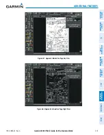
Page 503: ...IONAL FEATURES APPENDICES INDEX Figure 8 33 NOTAM Softkey Highlighted NOTAM Softkey Appears for Selected Airports Figure 8 34 Airport Information Page Local NOTAMs Local NOTAM on This Airport NOTAM So...

Page 504: ...L CNS FLIGHT MANAGEMENT HAZARD AVOIDANCE AFCS ADDITIONAL FEATURES APPENDICES INDEX CHART OPTIONS Pressing the CHRT OPT Softkey displays the next level of softkeys the chart options level Figure 8 21 P...

Page 505: ...OIDANCE AFCS ADDITIONAL FEATURES APPENDICES INDEX Pressing the HEADER Softkey shows the header view approach chart briefing strip on the screen Approach Chart Briefing Strip Figure 8 36 Approach Infor...

Page 506: ...EX Pressing the PROFILE Softkey displays the approach chart descent profile strip Approach Chart Descent Profile Strip Figure 8 38 Approach Information Page Profile View Full Screen Width Pressing the...

Page 507: ...FLIGHT MANAGEMENT HAZARD AVOIDANCE AFCS ADDITIONAL FEATURES APPENDICES INDEX If the chart scale has been adjusted to view a small area of the chart pressing the FIT WIDTH Softkey changes the chart siz...

Page 508: ...AIRPORT INFO 2 Press the FMS Knob to activate the cursor 3 Turn the large FMS Knob to highlight the AIRPORT INFO RUNWAYS or FREQUENCIES Box INFO Box shown 4 Turn the small FMS Knob to select the INFO...

Page 509: ...using the page menu option Selecting full screen On or Off 1 While viewing a terminal chart press the MENU Key to display the Page Menu OPTIONS 2 Turn the large FMS Knob to highlight the Chart Setup...

Page 510: ...he large FMS Knob to highlight the Chart Setup Menu Option and press the ENT Key Figure 8 43 Waypoint Information Page OPTIONS Menu 3 Turn the large FMS Knob to move to the COLOR SCHEME Option Figure...

Page 511: ...ond DA62 497 ADDITIONAL FEATURES SYSTEM OVERVIEW FLIGHT INSTRUMENTS EIS AUDIO PANEL CNS FLIGHT MANAGEMENT HAZARD AVOIDANCE AFCS ADDITIONAL FEATURES APPENDICES INDEX Figure 8 44 Arrival Information Pag...

Page 512: ...Display Definition Blank Line system is not configured for ChartView Contact a Garmin authorized service center for configuration System is configured for ChartView but no chart database is installed...

Page 513: ...sed issue of ChartView is installed NOTE A subdued softkey label indicates the function is disabled Select the MFD1 DB Softkey to place the cursor in the DATABASE window Scroll through the listed info...

Page 514: ...re shown in Figure 8 48 The EXPIRES date in yellow is the revision date for the next database cycle The DISABLES date in yellow is the date that this database cycle is no longer viewable NOT AVAILABLE...

Page 515: ...off scale area depicted on some charts Figure 8 49 shows examples of off scale areas indicated by the grey shading Note these areas are not shaded on the published chart These off scale areas appear o...

Page 516: ...WX and GO BACK The chart selection softkeys appear on the Airport Information Page Pressing the GO BACK Softkey reverts to the top level softkeys and previous page Pressing the CHRT OPT Softkey displa...

Page 517: ...OPTIONS Menu to Show Chart 3 Press the ENT Key to display the chart Navigation Map Page OPTIONS Menu Waypoint Airport Information Page OPTIONS Menu Figure 8 51 Option Menus When no terminal procedure...

Page 518: ...nimums are available that page appears If Airport Information pages are unavailable the Approach Chart for the airport is shown Selecting a chart 1 While viewing the Navigation Map Page Flight Plan Pa...

Page 519: ...sing the Joystick centers the chart on the screen The aircraft symbol is not shown on FliteCharts The Chart Scale Box displays a banner NOT TO SCALE and the Aircraft Not Shown Icon is displayed in the...

Page 520: ...he INFO 1 or INFO 2 Softkey has no effect Another source for additional airport information is from the INFO Box above the chart Figure 8 55 or to the right of the chart Figure 8 56 for certain airpor...

Page 521: ...ITIONAL FEATURES APPENDICES INDEX In the example shown in Figure 8 56 TAKE OFF MINIMUMS is selected Pressing the ENT Key displays the Take off Minimums and Departure Procedures Chart Figure 8 57 Figur...

Page 522: ...DIO PANEL CNS FLIGHT MANAGEMENT HAZARD AVOIDANCE AFCS ADDITIONAL FEATURES APPENDICES INDEX Pressing the STAR Softkey displays the Standard Terminal Arrival Chart if available Figure 8 59 Arrival Infor...

Page 523: ...Airport Taxi Diagram press the WX Softkey to display the information windows AIRPORT INFO 2 Press the FMS Knob to activate the cursor 3 Turn the large FMS Knob to highlight the INFO Box 4 Turn the sma...

Page 524: ...EL CNS FLIGHT MANAGEMENT HAZARD AVOIDANCE AFCS ADDITIONAL FEATURES APPENDICES INDEX CHART OPTIONS Pressing the CHRT OPT Softkey displays the next level of softkeys the chart options level Figure 8 50...

Page 525: ...MANAGEMENT HAZARD AVOIDANCE AFCS ADDITIONAL FEATURES APPENDICES INDEX Pressing the FIT WIDTH Softkey fits the width of the chart in the display viewing area In the example shown the chart at close ran...

Page 526: ...ADDITIONAL FEATURES APPENDICES INDEX Pressing the FULL SCN Softkey alternates between removing and replacing the data window to the right Press FULL SCN Softkey to Switch Between Chart on Full Screen...

Page 527: ...using the page menu option Selecting full screen On or Off 1 While viewing a terminal chart press the MENU Key to display the Page Menu OPTIONS 2 Turn the large FMS Knob to highlight the Chart Setup...

Page 528: ...the large FMS Knob to highlight the Chart Setup Menu Option and press the ENT Key Figure 8 66 Waypoint Information Page OPTIONS Menu 3 Turn the large FMS Knob to move to the COLOR SCHEME Option Figure...

Page 529: ...nd DA62 515 ADDITIONAL FEATURES SYSTEM OVERVIEW FLIGHT INSTRUMENTS EIS AUDIO PANEL CNS FLIGHT MANAGEMENT HAZARD AVOIDANCE AFCS ADDITIONAL FEATURES APPENDICES INDEX Figure 8 67 Approach Information Pag...

Page 530: ...8 69 Power up Page FliteCharts Database FliteCharts Database Power up Page Display Definition Blank Line system is not configured for FliteCharts Contact a Garmin authorized service center for configu...

Page 531: ...tive 180 days after the FliteCharts EXPIRES date is reached and is no longer available for viewing This date is shown as the DISABLES date After the disable date the SHW CHRT Softkey label appears sub...

Page 532: ...are shown here The EFFECTIVE date in yellow indicates the current date preceeds the date the FliteCharts database becomes effective The EXPIRES date in yellow is the revision date for the next databa...

Page 533: ...rmation Page by selecting the INFO Softkey until INFO 2 is displayed as shown in Figure 8 72 Both Airport Directories are available for downloading at flygarmin com However copy only one of the databa...

Page 534: ...heck fly garmin com for the current database The Airport Directory is always available for use after the expiration date When turning on the system the Power up Page indicates whether the databases ar...

Page 535: ...the year 2014 D Indicates the data is for Airport Directory 1 Indicates the first issue of the Airport Directory database for the year The Airport Directory EFFECTIVE date 13 JAN 14 is the beginning...

Page 536: ...or both must be provided to SiriusXM Satellite Radio to activate the entertainment subscription It is not required to activate both the entertainment and weather service subscriptions with the GDL 69A...

Page 537: ...s the ENT Key RADIO and INFO Softkeys Figure 8 75 XM Information Page Audio Radio ID Weather Products Window Data Radio ID LOCK Softkey is Used to Save Activation Data During Initial Setup If SiriusXM...

Page 538: ...ress the RADIO Softkey to show the XM Radio Page where audio entertainment is controlled Figure 8 76 XM Radio Page Volume Field Categories Field Channel List Active Channel ACTIVE CHANNEL AND CHANNEL...

Page 539: ...TEGORY The Category Box of the XM Radio Page displays the currently selected category of audio Categories of channels such as jazz rock or news can be selected to list the available channels for a typ...

Page 540: ...Accessing and Selecting Preset SiriusXM Channels Press PRESETS to Access the Preset Channels Softkeys Press MORE to Cycle Through the Preset Channels Press SET to Save Each Preset Channel Pressing the...

Page 541: ...GISTERING THE IRIDIUM SATELLITE SYSTEM A subscriber account must be established for each Iridium transceiver prior to using the Iridium Satellite System for telephone services Before setting up an Iri...

Page 542: ...play as shown in Figure 8 81 gives a graphical representation of the current disposition of voice and or data transmissions Table 8 5 describes symbology used on PHONE STATUS display Figure 8 81 Phone...

Page 543: ...D to display the Page Menu 2 Turn either FMS Knob to place the cursor on Disable Iridium Transmission 3 Press the ENT Key Internal Phone External Phone Description Phone is Idle Phone is ringing Phone...

Page 544: ...nswer an incoming call in the cockpit 1 Press the TEL Key on the appropriate audio panel 2 Press the ANSWER Softkey on the MFD Or While viewing the AUX TELEPHONE Page 1 Press the TEL Key on the approp...

Page 545: ...l the call is terminated To make a call 1 Press the TEL Key on the audio panel 2 Press the DIAL Softkey on the MFD A display similar to Figure 8 84 will be shown Or While viewing the AUX TELEPHONE Pag...

Page 546: ...MENT HAZARD AVOIDANCE AFCS ADDITIONAL FEATURES APPENDICES INDEX The following country codes may be used when calling other satellite telephone systems Satellite System Country Code Inmarsat 870 ICO 88...

Page 547: ...MENT HAZARD AVOIDANCE AFCS ADDITIONAL FEATURES APPENDICES INDEX 5 Press the ENT Key The system will begin calling the number as in Figure 8 86 Figure 8 86 System is Making the Connection When the phon...

Page 548: ...work Messages may be sent to an email address or text message capable cellular telephone Message length is limited to 160 characters including the email address The text messaging user interface is ma...

Page 549: ...edefined text message Table 8 6 Text Message Symbols VIEWING A TEXT MESSAGE WHEN RECEIVED When viewing MFD pages other than the AUX TEXT MESSAGING Page a pop up alert similar to Figure 8 89 will be di...

Page 550: ...t The pop up alerts may be enabled or disabled through the Page Menu Enabling disabling incoming text message pop up alerts 1 With the AUX TEXT MESSAGING Page displayed press the MENU Key on the MFD t...

Page 551: ...viewing the text message press the REPLY Softkey Or 1 Press the MENU Key to display the Page Menu 2 Turn either FMS Knob to place the cursor on Reply To Message 3 Press the ENT Key SENDING A TEXT MESS...

Page 552: ...be accessed by selecting the SYMBOLS Softkey See Figure 8 92 3 Press the ENT Key The cursor is now displayed in the MESSAGE field 4 Enter the desired message using any combination of entry methods as...

Page 553: ...Controller or combination of the FMS Knob on the controller and softkeys on the MFD The FMS Knob is used to enter letters and numbers or numbers can be entered from the MFD by selecting the NUMBERS So...

Page 554: ...email address Entry can be accomplished through a combination of the FMS Knob on the controller and softkeys on the MFD The FMS Knob is used to enter letters and numbers or numbers can be entered fro...

Page 555: ...mit the message TEXT MESSAGE BOXES Received text messages reside in the Inbox as Read or Unread messages The Outbox contains Sent and Unsent text messages Saved messages that are meant to be sent late...

Page 556: ...t the bottom left of the list window MANAGING TEXT MESSAGES The viewed messages may be listed according to the date time the message was sent or received the type of message read unread sent unsent et...

Page 557: ...he sorting selection is indicated at the bottom center of the list window Viewing the content of a text message 1 While viewing the AUX TEXT MESSAGING Page select the desired message box 2 Press the F...

Page 558: ...b Turn either FMS Knob to place the cursor on Mark Selected Message As Read c Press the ENT Key The message symbol now indicates the message has been opened Marking all messages as read 1 While viewin...

Page 559: ...e guidance to the pilot for returning the aircraft to the normal flight envelope This is perceived by the pilot as resistance to control movement in the undesired direction when the aircraft approache...

Page 560: ...ator is now showing where ESP will disengage as roll attitude decreases Roll Limit Indicator ESP Engage 45 Figure 8 99 ESP Roll Engagement Indication ESP NOT Engaged Roll Limit Indicator ESP Engage 45...

Page 561: ...t 75 Aircraft Roll Attitude 74 PITCH ENGAGEMENT ESP engages at 16 nose up and 22 nose down Once ESP is engaged it will apply increasing opposing force between 16 and 20 nose up and between 22 and 25 n...

Page 562: ...rection of the normal pitch attitude range for the aircraft There are no indications marking the pitch ESP engage and disengage limits in these nose up nose down conditions Figure 8 103 ESP Pitch Oper...

Page 563: ...to activate the flashing cursor 3 Turn the large FMS Knob to highlight the first empty scheduler message naming field 4 Use the FMS Knob to enter the message text to be displayed in the Alerts Window...

Page 564: ...4 Press the CLR Key to clear the message text If the CLR Key is pressed again the message is restored 5 Press the ENT Key while the message line is cleared to clear the message text Scheduler message...

Page 565: ...ight The system accesses the checklists from an SD card inserted into the top card slot of the MFD If the SD card contains an invalid checklist file or no checklist the Power up Page messages display...

Page 566: ...NEXT CHECKLIST is selected prior to checking all the checklist items CHECKLIST NOT FINISHED will be displayed in yellow text 8 Press the ENT Key If GO TO NEXT CHECKLIST is displayed when pressing the...

Page 567: ...in the box next to it The next line item is automatically highlighted for checking Either FMS Knob can be used to scroll through the checklist and select the desired checklist item Press the CLR Key...

Page 568: ...eing written to the SD card LOGGING DATA is displayed The csv file may be viewed with Microsoft Excel or other spreadsheet applications The following is a list of data parameters the G1000 system is c...

Page 569: ...TURES APPENDICES INDEX The file containing the recorded data will appear in the format shown in Figure 8 109 This file can be imported into most computer spreadsheet applications log_140210_104506_KIX...

Page 570: ...o 1 Turn the large FMS Knob to select the AUX page group 2 Turn the small FMS Knob to select VIDEO and display the AUX VIDEO Page The video display softkeys shown below appear on the AUX VIDEO Page Fi...

Page 571: ...adjust display brightness in five percent increments from 0 to 100 3 Press the CNTRST or CNTRST to adjust display contrast in five percent increments from 0 to 100 4 Press the SAT or SAT to adjust dis...

Page 572: ...creases video display magnification between 1x and 10x The RANGE Knob can be used to increase or decrease the range setting on the map display or zoom in and out on the video display While in the Spli...

Page 573: ...e of invalid SVT data the PFD display reverts to the standard blue over brown attitude display SVT becomes disabled without the following data resources Attitude data Heading data GPS position data 9...

Page 574: ...indicating the direction to fly to correct the unusual attitude condition The display shows either a brown or blue colored bar at the top or bottom of the screen to represent earth or sky This is inte...

Page 575: ...ibed to SiriusXM Ensure the SiriusXM subscription has been activated Perform a quick check of the circuit breakers to ensure that power is applied to the Data Link Receiver For troubleshooting purpose...

Page 576: ...ve channel field Data Link Receiver updating encryption code NO SIGNAL XM Radio Page active channel field Weather Datalink Page center of page Loss of signal signal strength too low for receiver LOADI...

Page 577: ...rts Window displays text messages for up to 64 prioritized alert messages Pressing the ALERTS Softkey displays the Alerts Window Pressing the ALERTS Softkey a second time removes the Alerts Window fro...

Page 578: ...nes when specific system conditions are met See the Alert Level Definitions Section for more information The annunciation tone may be tested from the AUX System Status Page Testing the system annuncia...

Page 579: ...ion alert text is shown in yellow in the Annunciation Window and is accompanied by a single chime and a flashing CAUTION Softkey annunciation Pressing the CAUTION Softkey acknowledges the presence of...

Page 580: ...osed REAR DOOR OPEN Rear door is not closed L ENG FIRE Left engine fire detected R ENG FIRE Right engine fire detected L ENG TEMP Left engine coolant temp is 105 deg C R ENG TEMP Right engine coolant...

Page 581: ...ure is high DEIC PRES LO De icing pressure is low L ECU A FAIL Left engine ECU A has failed R ECU A FAIL Right engine ECU A has failed L ECU B FAIL Left engine ECU B has failed R ECU B FAIL Right engi...

Page 582: ...ce Alert Alert Trigger Minimums Minimums Issued when the aircraft transitions through the minimum descent altitude decision height MDA DH Vertical Track Aircraft is one minute from Top of Descent issu...

Page 583: ...00 Pilot s Guide for the Diamond DA62 SYSTEM OVERVIEW FLIGHT INSTRUMENTS EIS AUDIO PANEL CNS FLIGHT MANAGEMENT HAZARD AVOIDANCE AFCS ADDITIONAL FEATURES APPENDICES INDEX 569 APPENDIX A Figure A 4 Audi...

Page 584: ...responsible LRUs Refer to the Airplane Flight Manual AFM for additional information regarding pilot responses to these annunciations Figure A 5 G1000 System Failure Annunciations GDC 74A GRS 77 GMU 44...

Page 585: ...during normal operation AHRS operation may be degraded if GPS signals are not present see AFM Display system is not receiving valid heading input from AHRS Display system is not receiving valid true...

Page 586: ...eds service Return unit for repair MANIFEST PFD1 software mismatch communication halted The PFD and or MFD has incorrect software installed The G1000 system should be serviced MANIFEST MFD1 software m...

Page 587: ...G1000 system should be serviced PFD1 DB ERR PFD1 obstacle database error exists MFD1 DB ERR MFD1 obstacle database missing The obstacle database is present on another LRU but is missing on the specifi...

Page 588: ...DB MISMATCH Terrain database mismatch The PFD and MFD have different terrain database versions or types installed Check the AUX SYSTEM STATUS Page to determine versions or regions Also check the AUX S...

Page 589: ...p configuration memory The G1000 system should be serviced COM2 CONFIG COM2 config error Config service req d The COM2 configuration settings do not match backup configuration memory The G1000 system...

Page 590: ...2 needs service Return unit for repair NAV1 RMT XFR NAV1 remote transfer key is stuck The remote NAV1 and or NAV2 transfer switch is stuck in the enabled or pressed state Press the transfer switch aga...

Page 591: ...DL69 FAIL GDL 69 has failed A failure has been detected in the GDL 69 The receiver is unavailable The G1000 system should be serviced MANIFEST GDL software mismatch communication halted The GDL 69 has...

Page 592: ...do not match backup configuration memory The G1000 system should be serviced MANIFEST GMA1 software mismatch communication halted The audio panel has incorrect software installed The G1000 system sho...

Page 593: ...new navigation database update Verify that stored flight plans contain correct waypoint locations TIMER EXPIRD Timer has expired The system notifies the pilot that the timer has expired DB CHANGE Dat...

Page 594: ...light plan The lateral flight plan contains a procedure turn vector or other unsupported leg type prior to the active vertical waypoint This prevents vertical guidance to the active vertical waypoint...

Page 595: ...1 CARD 2 REM Card 2 was removed Reinsert card The SD card was removed from the bottom card slot of the specified PFD or MFD The SD card needs to be reinserted PFD1 or MFD1 CARD 1 ERR Card 1 is invalid...

Page 596: ...g so may cause the preflight system test to fail or never to start Cycle power to the servos if this occurs Preflight system test failed aural alert sounds at failure Table 7 5 AFCS Status Alerts SVS...

Page 597: ...583 APPENDIX A SVS TERRAIN STATUS ANNUNCIATIONS Alert Type PFD MFD TERRAIN SVS Page Annunciation Aural Message System Test Fail Terrain System Failure Terrain Alerting is disabled None No GPS positio...

Page 598: ...PPESEN DATABASES The Jeppesen navigation database is updated on a 28 day cycle The ChartView database is updated on a 14 day cycle If the ChartView database is not updated within 70 days of the expira...

Page 599: ...Update Confirmation 6 Turn the G1000 system OFF and remove the SD card from the top card slot 7 Repeat steps 2 through 6 for PFD1 8 Apply power to the system and press the ENT Key to acknowledge the...

Page 600: ...abases stored on each card Figure B 4 Correct Database Locations PFD MFD Since these databases are not stored internally in the displays a Supplemental Data Card containing identical database versions...

Page 601: ...he SD cards on the PFD and the MFD to ensure that all databases are synchronized throughout the system After power up the system compares all copies of each applicable database If similar databases do...

Page 602: ...ion If the Display Database Softkey is pressed repeatedly the softkey will switch between PFD1 and MFD1 Database status information in the Database Window will reflect the database of the selected PFD...

Page 603: ...ata Card Equipment required to perform the update is as follows Windows compatible PC computer running Windows XP Vista or Windows 7 SD Card Reader SanDisk SDDR 93 SanDisk SDDR 99 Verbatim 96504 or eq...

Page 604: ...as seen in Figure B 6 9 Remove and reapply power to the system 10 Turn the large FMS Knob to select the AUX Page group on the MFD 11 Turn the small FMS Knob to select the System Status Page 12 Press t...

Page 605: ...RES APPENDICES INDEX 591 APPENDIX B Figure B 9 GRS Magnetic Field Variation Database Update Prompt Loading the magnetic field variation database update 1 With OK highlighted as shown in figure B 9 pre...

Page 606: ...Pilot s Guide for the Diamond DA62 190 01895 00 Rev A SYSTEM OVERVIEW FLIGHT INSTRUMENTS EIS AUDIO PANEL CNS FLIGHT MANAGEMENT HAZARD AVOIDANCE AFCS ADDITIONAL FEATURES APPENDICES INDEX 592 APPENDIX...

Page 607: ...ce AUX auxiliary AWOS Automated Weather Observing System B ALT barometric altitude BARO barometric setting BATT battery BC backcourse Bearing The compass direction from the present position to a desti...

Page 608: ...ation ELEV elevator EMERGCY emergency EMI Electromagnetic Interference ENDUR endurance Endurance Flight endurance or total possible flight time based on available fuel on board ENG engine ENGD engaged...

Page 609: ...travelling relative to a ground position Ground Track see Track GRS Garmin Reference System GS Ground speed GTX Garmin Transponder HA Hold Terminating at Altitude HDG heading Heading The direction an...

Page 610: ...N manifold pressure inches Hg MAN SQ Manual Squelch MAP Missed Approach Point MASQ Master Avionics Squelch MAX maximum MAXSPD maximum speed overspeed MDA barometric minimum descent altitude MET manual...

Page 611: ...SID Standard Instrument Departure SIGMET Significant Meteorological Information Sim simulator SLP SKD slip skid SMBL symbol SPD speed SPI Special Position Identification SPKR speaker SQ squelch SRVC S...

Page 612: ...scend climb from a current position and altitude to a defined target position and altitude based upon current groundspeed VFOM Vertical Figure of Merit VFR Visual Flight Rules VHF Very High Frequency...

Page 613: ...te Augmentation System MSAS covers mainly Japan and parts of northern Australia How does SBAS affect approach operations Both LNAV VNAV and LPV approaches use the accuracy of SBAS to include vertical...

Page 614: ...flight plans with an approach a departure or an arrival the G1000 uses the waypoint information from the current database to define the waypoints If the database is changed or updated the G1000 System...

Page 615: ...an This procedure is performed on the MFD from the Active Flight Plan Page by highlighting the desired waypoint and selecting the ACT LEG Softkey then the ENT Key to approve the selection The GPS then...

Page 616: ...r a missed approach how can the same approach be re selected How can a new approach be activated NOTE Do not attempt to reactivate the current approach prior to crossing the missed approach point MAP...

Page 617: ...interrogator and accompanying data link to provide a five second update rate TIS and TAS TCAS have similar ranges TIS LIMITATIONS NOTE TIS is not intended to be used as a collision avoidance system a...

Page 618: ...ypically remain relatively accurate and may be used to assist in spotting traffic The following errors are common examples When the client or intruder aircraft maneuvers excessively or abruptly the tr...

Page 619: ...rivate Airport Heliport NAVAIDS Item Symbol Intersection LOM compass locator at outer marker NDB non directional radio beacon VOR VOR DME VOR ILS VORTAC TACAN BASEMAP Item Symbol Interstate Highway St...

Page 620: ...bled Surface Analysis display enabled Freezing Levels display enabled Winds Aloft display enabled County Warnings display enabled Cyclone Warnings display enabled Loss of hazard avoidance feature loss...

Page 621: ...above or within 100 ft below the aircraft altitude Yellow terrain is between 100 ft and 1000 ft below the aircraft altitude Black terrain is more than 1000 ft below the aircraft altitude Figure F 1 Te...

Page 622: ...onnected to another phone Phone dialed is busy Phone is dialing another phone Phone has failed Phone status not known Phone is disabled Phone is reserved for data transmission Calling other phone or i...

Page 623: ...lights 124 ANT BFO 114 Antenna Stabilization 367 Antenna Tilt 364 AOPA 461 519 586 587 AOPA Airport Directory 527 Approach 600 Activating 243 ILS 454 Loading 205 240 242 Missed 456 Removing 243 Approa...

Page 624: ...e procedure 210 211 An individual waypoint 210 Flight Plan Items 209 Density Altitude 249 Departure Procedure 201 215 233 235 Select 233 236 240 243 Time 247 Timer 40 Departure procedure chart 486 507...

Page 625: ...g 46 Heading Bug 46 Heading Select Mode HDG 436 447 HI SENS 111 Horizontal Scan 360 361 362 363 364 368 369 Horizontal Situation Indicator HSI 46 55 HSI double green arrow 103 HSI magenta arrow 103 HS...

Page 626: ...d protection autopilot 459 P Page groups 28 31 Page menus 26 Parallel Track 214 215 Pilot profiles 36 37 Pilot Weather Report PIREP 316 325 326 328 345 Pitch Hold Mode PIT 420 Pitch modes flight direc...

Page 627: ...DATA 144 145 154 Top of Descent 270 271 TOPO SCALE 146 Total flight hours 86 Track Indicator 55 Traffic Annunciation 47 Traffic Advisory System TAS 360 361 363 364 365 366 Traffic Advisory TA 360 Tra...

Page 628: ...e level ADF 112 114 VOR Nearest 181 182 VOR selection 103 VSI 272 VS TGT 228 270 W WAAS 254 446 575 599 Waypoint Automatic sequencing 600 601 Skipping 601 Waypoint Pages WPT 29 Waypoint Selection Subm...

Page 629: ......

Page 630: ...Garmin AT Inc 2345 Turner Road SE Salem OR 97302 U S A p 503 391 3411 f 503 364 2138 Garmin Europe Ltd Liberty House Houndsdown Business Park Southampton Hampshire SO40 9LR U K p 44 0 23 8052 4000 f 4...

Reviews: