


37-1-615 Page 38
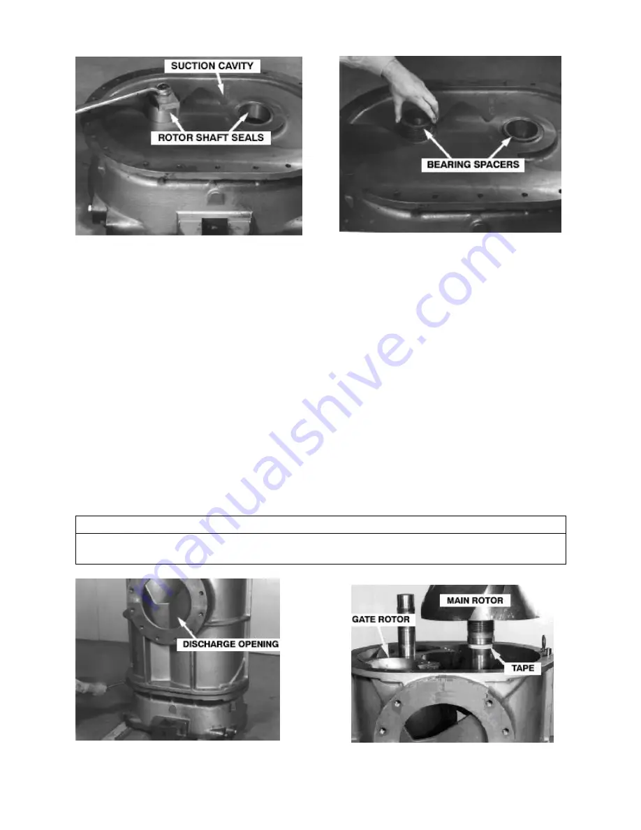
FIGURE 7-1
FIGURE 7-2
With the spacer seated against the face of the rotor, spin the spacer on the shaft several times to
evenly spread the Loctite 620. Make sure there are no burrs on either end of the spacer or end of
the rotor. Place tape around the shaft to prevent the spacer from sliding off as shown in
FIGURE 7-4.
3. Place .030
” thick aluminum shim (20) on the gear end bearing carrier (4). The pointed section of
the shim is positioned on the machined surface of the carrier to match the contour of the housing.
Lower the housing (1), as level as possible, onto the carrier with the discharge opening up
(FIGURE 7-3), and the inlet opening matching the cavity side (FIGURE 7-1), of the carrier.
Engage the dowel pins (45) with matching holes in the carrier with care. Tighten the gear carrier
(4) end bearing to housing (1) with screws (50, 51)and lockwashers (55) evenly so the dowel pins
will not be damaged.
4. Coat the inside of both shaft seals (18, 19) and the grooved end of the bearing spacers (16, 17)
with
“Moly” type grease for seal break-in purposes. Be sure the ends of the rotors (2, 3) and
machined face of the carrier are free of burrs and dirt. The easiest method of assembly is to
lower the gate rotor into the housing first (FIGURE 7-4). The gear end shaft extension of the
rotors, with the bearing spacer installed in Step 2, goes down. Rotors must be suspended plumb
when lowering so the shaft extension and bearing spacer can be carefully guided through the
close fit of the shaft seal without damage to the babbitt lining.
NOTICE
If rotors are installed in reverse of above instructions, the gate rotor bearing spacer O.D. will
drag on the main rotor lobe and be damaged.
FIGURE 7-3
FIGURE 7-4