


37-1-615 Page 27
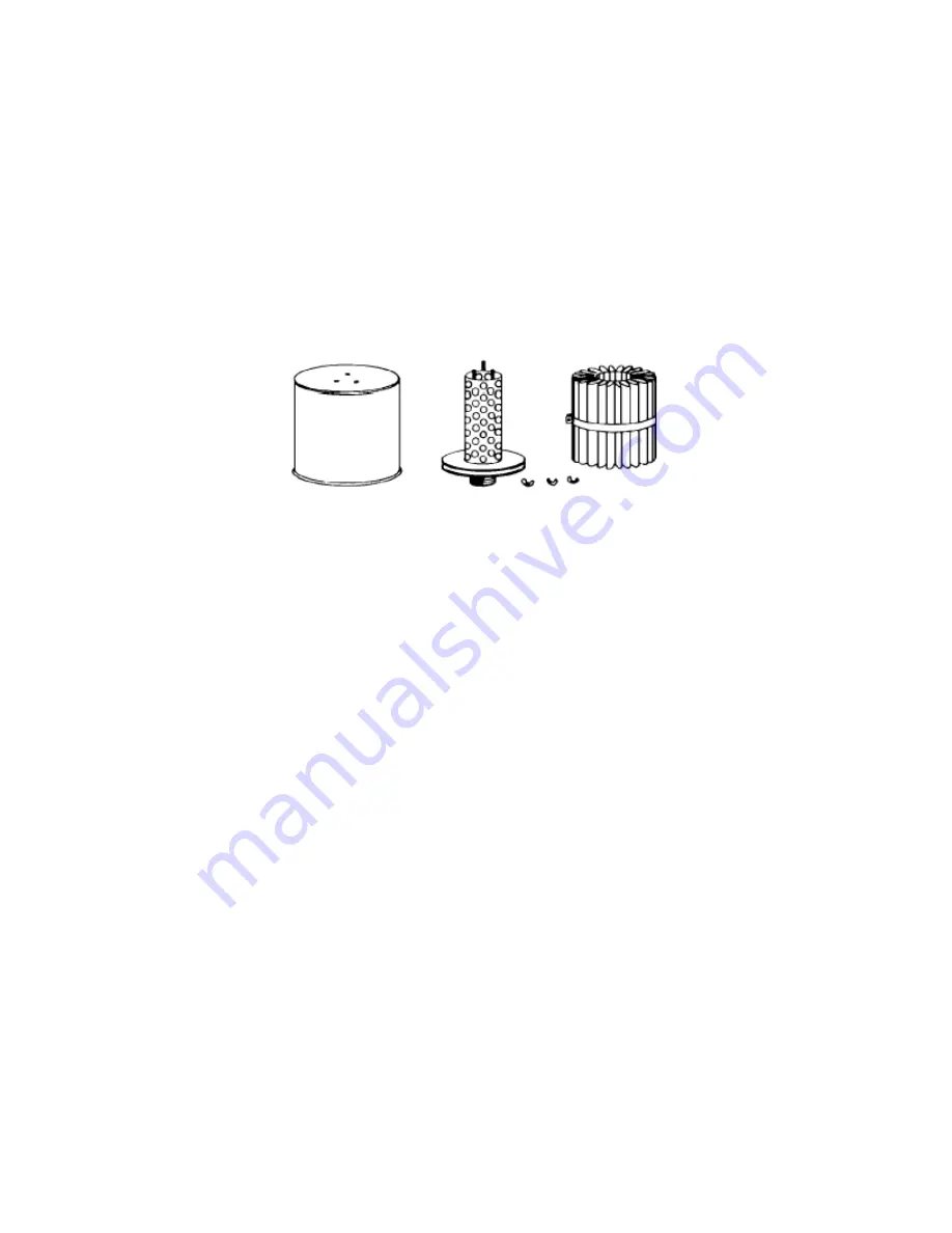
Dry Type Filter and Filter-Silencer
(FIGURE 4-6)
– When the outside surface of the element appears to
be evenly coated with dirt, it should be cleaned as follows:
1.
Remove wing nuts and lift off the hood.
2.
Loosen the outside retaining strap to remove the media.
3.
Vibrate or blow off heavy dirt accumulation.
4.
If required, wash the media in any carbon base commercial solvent and blow off the excess
solvent.
5.
Allow to dry and examine for damage or conditions requiring replacement.
Because the media in the dry type filter is of wool felt, it may become impregnated with oil or water, if
present in any large degree. Corrosive gases may also attack the media. While such conditions are not
common, they should be kept in mind.
FIGURE 4-6 – DRY TYPE FILTER AND FILTER-SILENCER
DISCHARGE SILENCER
– A drain may be provided in the silencer at the lowest point for draining
condensate. Draining intervals will depend upon humidity conditions and must be established by the
user.
ROTOR SHAFT SEALS
– Rotors have a labyrinth type shaft air seal to minimize air leakage along the
shaft from the compression chamber. More air will leak through the seals at the discharge end since they
are under higher air pressure. Excessive air leakage indicates shaft seal failure.
The air seal consists of two parts, a hardened steel bearing spacer with grooves cut into the outside
diameter, and a steel-backed babbitt ring (shaft seal) pressed into the bearing carrier. The grooved end
of the spacer and the shaft seal bore have a close fit when cold. When the blower reaches operating
temperature for the first time, the babbitt embeds slightly into the grooves, forming a close running fit to
control air leakage along shaft. No maintenance is required, except that bearing carrier removal usually
will destroy the babbitt grooving and the shaft seal must be replaced. Shaft seals that have been in
operation should not be reused as excessive leakage may result. The bearing spacer can be reused
unless damaged. After installation of new seals, rotation of the blower may be tight for a few turns until
bearing spacer grooves cut running ways into the babbitt. For seal replacement refer to Disassembly
Section, page 36, and Assembly Section, page 40
BEARING OIL SEALS
– Oil leakage along each shaft from the oil sumps is prevented by a lip type seal
pressed into the bearing carrier. These seals are unidirectional lip seals. The hydrodynamic spiral in the
Teflon lip pumps the oil back into the sump. Usual causes of seal failure are: high temperature, rough
surface on bearing spacer, damage during installation, and improper seal used. The radius at the end of
the bearing spacer and O.D. should be highly polished to prevent seal lip damage during installation. Use
only seals shown in parts list as they have been selected for blower service. They must be installed in
the correct location and with the proper orientation or the oil will be pumped out of the pump. Rotation
arrows and color coding are used to distinguish clockwise seals from counterclockwise seals, see
FIGURE 7-13, Assembly Instructions page 44.