IDL 101
INSTALLATION
HB_IDL101_E_V222.doc
17
Gantner Instruments Test & Measurement GmbH
0
V
A
B
R
X
T
X
C
O
M
S
O
U
R
C
E
A
In
+
A
In
-
RUN
ERR
I/O
0
2
I/O
0
4
+
1
0.
.3
0V
RS 232
RS 485
SUPPLY
S
O
U
R
C
E
A
In
+
A
In
-
S
O
U
R
C
E
A
In
+
A
In
-
S
O
U
R
C
E
A
In
+
A
In
-
S
O
U
R
C
E
A
In
+
A
In
-
S
O
U
R
C
E
A
In
+
A
In
-
A
O
ut
+
I/O
1
2
I/O
1
4
I/O
1
6
I/O
1
5
I/O
0
6
I/O
0
8
I/O
1
0
I/O
0
1
I/O
0
3
I/O
1
1
I/O
1
3
I/O
0
5
I/O
0
7
I/O
0
9
INTELLIGENT DATA LOGGER
AD
R
A
GN
D
DIGITAL
A
GN
D
A
GN
D
A
GN
D
A
GN
D
A
GN
D
A
GN
D
1
2
3
4
5
6
1
2
3
4
5
6
7 8
9
10
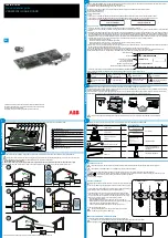
3.4. Front of the Appliance / Pin Assignment
At the front of the
Datalogger IDL 101 there are the attachment accessories and display elements described in the
following figure.
Figure 3.1 Front of the IDL 101
Elements:
Number
Meaning
Number
Meaning
1
Status LEDs for Digital I/Os
6
6 analog inputs
2
LED RUN (green)
7
Power supply
3
LED ERR (red)
8
RS 485 interface
4
Rapid Bus Link Plug
9
RS 232 interface
5
Analog Output
10
16 digital I/Os
Table 3.1 Elements on the front of the IDL 101
Pin
Assignment:
terminal
meaning
terminal
meaning
A
RS485-bus interface A
I/Ox
Digital I/Ox
B
RS485-bus interface B
SOURCE
Supply for analog Input
+10..30 VDC
voltage
AIn +
Analog Input + Ground
0 V
voltage supply -
AIn -
Analog Input – Ground
RX
RS232 Receive
AGND
Analog Input
TX
RS232 Transmit
AOUT +
Analog
COM
RS232 Ground
AGND
analog output ground
* The terminal designations A and B are exchanged, compared with the PROFIBUS-definitions, for all devices of the ISM series “100“ and the
Datalogger IDL 101. This means that in multi-vendor-systems the bus lines A and B must be exchanged when they are connected to a device of the
ISM-line or a Datalogger IDL 101.
Table 3.2 Pin assignment