G
AMATRONIC
E
LECTRONIC
I
NDUSTRIES
L
TD
.
Centric 3x480 Vac, Installation Guide, rel. 2.2
68
Figure 70: Ac output voltage display, per module
For each module with an “out of range” output voltage, note which module it is, which phase or
phases are out of range, and what the voltage is. Then, navigate to
“Main menu > Setup > Modules > Ac output voltage adjustment”
and change the output voltage for the problematic module phase. You must tap “Confirm” for each
module that you update.
10. When you have verified that all of the slave systems have output voltages within ±2 V of the master
system, put each system in bypass mode
(Main menu > Operation > Transfer > Transfer load to bypass).
11. For each slave system, compare the output voltage of each phase to that of the master system, as
you did above, except that now the systems are in bypass mode. Any voltage difference should be no
greater than 2 Vac.
12. Return all of the systems to inverter mode.
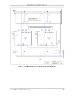
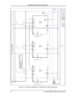
13. Move the output circuit breaker of each UPS to the ON position. (CB5 in the connection diagrams -
Figure 71, Figure 72, Figure 73).
14. Compare the output current from each pair of systems. Under full load, the difference in output current
between any two systems should not exceed ±10 % of the total system output current.
15. The parallel systems are now ready for use for any loads up to the maximum rated output in kW of the
combined systems.


