background image


evolution G-35 H 

Service Manual 


36/45 

Issue 1.9 

Ref. NR-00103-ENG 

http://www.gamapur.com/


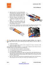
a)  Determine the direction in which the plate must move; this depends on which micro has 

been passed. 

b)  Locate  the  slide  for  the  manual  activation  of  the  directional  valve  in  the  hydraulic 

distributor: this is located on the same side of the machine towards which the activation 
plate must work. 

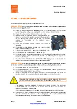
c)  Turn  the  general  switch  ON,  press  the  POWER  CONTROL  key  and  the  MOTOR  key. 

With the manual valves of the coupling block open, point the gun at a waste container. 

d)  Press  the  manual  slide  of  the  directional  valve  and  hold  it  until  the  activation  plate  is 

centred between the two run end micros. 

e)  If  when  pressing  the  slide,  it  moves  freely,  the  excess  run  is  due  to  an  electrical 

problem. Press the MOTOR key  and the NORMAL key;  press the run end micros and 
check  whether  the  reels  are  changed  and  the  direction  indicator  lights:  if  the  reels  are 
not  changed  or  the  direction  indicator  lights  fail  to  come  on,  there  is  an  electrical 
problem in the run end micro or in the reels of the directional valve. 
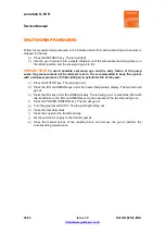
5. 

Over Pressure Safety Switch 

Each  metering  pump  is  protected  by  a  safety  pressure  switch  factory  set  to  limit  the  pressure 
depending on the size of the pumps installed  in the unit. For 

1.2

 and 

0.8 

size pumps, the limit 

pressure  set  in  the  factory  is  270  bar  (3900  psi).  When  the  limit  pressure  is  reached,  the 
pressure  switch  interrupts  the  electrical  supply  to  the  directional  valve,  stopping  the  pumps. 
When  the  pumps  stop,  the  direction  indicator  lights  will  go  out  and  an  alarm  will  be  activated 
that  will  be  shown  on  the  control  panel  (3  if  the  excess  pressure  is  caused  in  the  Isocyanate 
circuit or 4 if it is caused in the Polyol circuit). 

When  the  pressure  reaches  lower  values  than  the  established  limit,  the  metering  pumps  will 
restart. However, the causes of the excess pressure must be determined and corrected. 


Summary of Contents for evolution G-35 H

Page 1: ...carefully read all the technical and safety documentation included in this manual Pay special attention to the information to know and understand the operation and the conditions of use of the unit A...

Page 2: ...uct Use of heating devices pumping equipment dispensers or other parts or accessories with the Product that have not been approved or manufactured by HI TECH Failure to follow the operating instructio...

Page 3: ...ation and the conditions of use of the unit All of the information is aimed at enhancing User Safety and avoiding possible breakdowns derived from the incorrect use of the unit WARNING establishes inf...

Page 4: ...r Deal with the waste caused according to current regulations Disconnect the unit from the power supply before carrying out any operation inside the electrical console The electrical maintenance of th...

Page 5: ...on transformer that enables effective heating up to a total hose length of 305 ft for foam and 256 ft for polyurea The system includes an innovative hose heating concept in which the copper heating el...

Page 6: ...unit must only be carried out by a qualified electrician Mechanical Maximum working pressure P1 with pumps 1 2 ______________________ 240 bar 24 MPa Maximum production ratio 1 1 with pumps 1 2 _______...

Page 7: ...evolution G 35 H Service Manual 7 45 Issue 1 9 Ref NR 00103 ENG http www gamapur com Figure 1 General Description GENERAL DESCRIPTION...

Page 8: ...aulic Pressure Gage Indicates the pressure in the hydraulic drive system 8 Isocyanate Pressure Gage Indicates the pressure in the Isocyanate system 9 Isocyanate Safety Pressure Switch Deactivates the...

Page 9: ...ulic system the NORMAL or RETRACT key must be activated HIDRAULYC PUMP CONFIGURATIONS FOR 18CC PUMPS BOSCH REXROTH FOR 20CC PUMPS VICKERS UP TO 155 bar Limiting of pressure with pin for low pressure h...

Page 10: ...control panel displays to Metric or English Set to EU for the pressure to be shown in bar and the temperature to be shown in degrees Celsius Set to USA for the pressure to be shown in psi and the tem...

Page 11: ...is value by pressing the UP DOWN keys Once the change is made press the MODE key once more for the new value to be entered into memory and to select the next parameter for setting The modification mod...

Page 12: ...ith two hose transformer power locate the DIP Hose ISO and the DIP Hose RESIN to ON position if the hoses have TCS for the temperature control system or OFF position if the hoses not have TCS Please b...

Page 13: ...l the amperage flashes press the UP DOWN keys to enter the number of amps required and press the MODE key once more to enter the value into memory Refer to the table shown below to select the power th...

Page 14: ...displayed in psi and the temperature in degrees Fahrenheit Please be aware that after manipulating the DIP selector you should switch off the unit so the change in detected buy the board 7 Counter Ind...

Page 15: ...et off The ratio control parameters are factory set When the key is active the led in its center will come on 11 Normal Key Activates the normal operation of the machine When the key is active the led...

Page 16: ...Excessive POL Pressure deactivates the directional valve and the heating system Check the product pressure Check the number 11 led of the printed circuit it must be lit Check the over pressure safety...

Page 17: ...ucer if there is no reading Press the ratio key to cancel the function 11 000000 Cycle Pre selection made deactivates the directional valve Press the MODE key to reset the counter Set the cycle select...

Page 18: ...00001 Magnet holder tools 1x HT 00003 Pin extractor 1x KT 00040 PKG Kit adaptation Fast Lock 1x Inside the console there is a terminal strip for connecting the principal electrical wire not supplied...

Page 19: ...il is not more than 80 of its maximum capacity 63 Lts 16 6 gal Use the visual level indicator of temperature on the tank as a reference because the maximum temperature limit 80 C 176 F coincides with...

Page 20: ...ors of the Isocyanate and Polyol hoses the connectors are of different sizes to make it impossible for connections to be swapped Figure 3 Method of union of the Hoses WARNING To join the hoses togethe...

Page 21: ...h of hose installed If you add or eliminate sections of hose make sure the output voltage of the transformer to which it is connected is suitable for the resulting total length Otherwise change the co...

Page 22: ...t to kink or excessively bend the hoses Do not roll up the hoses with a radius of under one meter 4 feet l Connect the air hoses m Connect the hoses to the connectors of the coupling block of the gun...

Page 23: ...ity and produce electrical discharges Before using the unit the residual air and oil from factory testing must be eliminated To purge the whole circuit proceed as follows f Pressurize the transfer pum...

Page 24: ...he two leds will light i Press the ISO and RESIN keys under the HEATERS display when the products in the hoses reach the working temperature The two leds will light PRECAUTION To avoid excessive press...

Page 25: ...em with a minimum pressure of 30 bar 400 psi to extend the life of the seals c Press the MOTOR key The led will go out d Press the ISO and RESIN keys under the heater temperature display The two leds...

Page 26: ...them in the drums of the DOTP cleaning agent d Place a vessel under the coupling block to gather up the products contained inside the machine e Open the manual valves on the coupling block and press...

Page 27: ...l valves on the coupling block and press the MOTOR and NORMAL keys to start up the dosing pumps f Allow the products to come out until you see that only DOTP cleaning agent comes out free of impuritie...

Page 28: ...ts used in the process carefully read the safety information provided by your supplier Deal with the waste caused according to current regulations Disconnect the unit from the power supply before carr...

Page 29: ...y by deactivating the POWER CONTROL The thermostat will not reset until the temperature in the heater is below 120 C 248 F If the temperature in the Isocyanate heater or the Polyol heater is over 120...

Page 30: ...each element is as shown in the table according to the installed power and voltage Table 1 Elements Values List W V x1 x2 x4 x6 450 230 117 2 58 2 29 2 19 2 900 230 58 2 29 2 14 2 9 2 900 400 177 2 8...

Page 31: ...ww gamapur com 4 Temperature The control panel automatically detects any fault in the operation of the temperature If the fault occurs replace the probe paying special attention not to damage it when...

Page 32: ...heated 5 The hose display shows the symbol 6 The automatic switch is triggered 3 SOLUTIONS 1 Hose Length The evolution G 35 H has been designed to work with a maximum hose length of 93 meters 310 ft A...

Page 33: ...e the Fast Lock connector from the last section of hose and make a bridge on the connection immediately before d Restore the power supply press the POWER CONTROL key and the ISO and RESIN keys under t...

Page 34: ...ts are in the correct working position before determining the existence of a fault PROBLEMS SOLUTIONS The pumps fail to maintain the pressure when the unit is shut down 1 There are pressure difference...

Page 35: ...the decompensation is the consequence of a problem in the pumping system 3 Cavitation Cavitation occurs when the metering pump requires a larger volume of material than that supplied by the feeding sy...

Page 36: ...r the reels are changed and the direction indicator lights if the reels are not changed or the direction indicator lights fail to come on there is an electrical problem in the run end micro or in the...

Page 37: ...electric motor is protected by an overload safety switch that triggers when the motor draws excessive current Disconnect the machine from the power supply allow the motor to cool open the control pan...

Page 38: ...ied electrician To avoid damage caused by the impact of pressurized fluids do not open any connection or perform maintenance work on components subject to pressure until the pressures have been comple...

Page 39: ...of the resistance must be as shown in Table 1 on pag 30 d Apply Teflon or sealing paste to the thread and assemble the element into its housing e Reconnect the wires to the terminal block make sure t...

Page 40: ...ch year as indicated below a Depressurise the unit and disconnect it from the power supply Clean the hydraulic tank lid to prevent foreign bodies from falling into the tank when the lid is removed b R...

Page 41: ...ar hits or marks that may affect the normal functioning of the pump Check the condition of the ISO pump lubricant daily Change the DOTP if it becomes gelatinous or darker Gel formation is due to moist...

Page 42: ...risk of moisture contamination or contamination through the reaction with the solvent used in the cleaning operation To check the product inlet filters proceed as follows a Disconnect the unit from th...

Page 43: ...the gaskets and the seals are in a good condition the plasticizer will not have to be changed so frequently To replace the plasticizer proceed as follows a Project the gun until the Isocyanate meterin...

Page 44: ..._______________________________________ 24 Shutdown proedures __________________________________________ 25 Cleaning ____________________________________________________ 26 long term shutdown procedur...

Page 45: ...00103 ENG http www gamapur com Figure 1 General Description ___________________________________ 7 Figure 2 Control Panel ________________________________________ 11 Figure 3 Method of union of the Hos...

Reviews: