


evolution G-35 H
Service Manual
14/45
Issue 1.9
Ref. NR-00103-ENG
http://www.gamapur.com/
3.
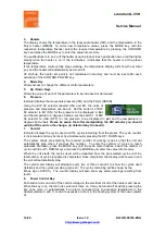
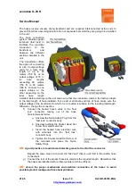
Heaters
The display shows the temperature in the Isocyanate heater (ISO) and the temperature in the
Polyol heater (RESIN). To enter new temperature values, press the MODE key until the
respective temperature flashes
;
select the required temperature by pressing the UP/DOWN
keys
and press the MODE key to enter the value into memory.
The pushbuttons turn on or off the heater of each product. Each pushbutton has a led that lights
steady when the heater is on; if the led flashes, it indicates that the heater is at the preset
temperature.
If the temperature control probe stops working, the temperature display will show the symbol
(---)
and the heater will automatically be turned off.
AT start-up, the heater set point is not maintained in memory and must be reset after each
activation of the CONTROL POWER key.
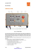
4.
Mode Key
Allows access to change the different control parameters.
5.
Up / Down Keys
Allows the value of each of the parameters to be increased or decreased.
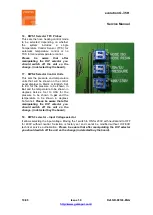
6.
Pressure
Indicator displays the Isocyanate pressure (ISO) and the Polyol (RESIN)
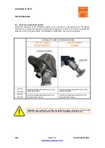
Using the DIP S2 selector labeled USA and EU, the units of
pressure and temperature can be set. Set the switch 1 of DIP
S2 selector to EU (ON) for the pressure to be displayed in
bar
and the temperature in degrees Celsius; set the switch 1 of DIP
S2 selector to USA (OFF) for the pressure to be displayed in
psi
and the temperature in
degrees Fahrenheit.
Please be aware that after manipulating the DIP selector you should
switch off the unit so the change. (in detected buy the board).
7.
Counter
Indicator displays the cycles used and the cycles remaining from the preset. The cycle counter
is incremental and may be reset by simultaneously pressing the UP / DOWN keys.
The system allows pre-selecting the required number of working cycles so that the unit will
automatically stop when it reaches this number. To enter the number of cycles to reach
automatic shutdown, press the MODE key until the cycle meter flashes, select the number of
cycles with the UP / DOWN keys
and press the MODE key
to enter the value into memory.
When the unit starts, the cycles used will be deducted from the pre-selected cycles until the
total number of cycles requested is completed. Once completed, the display will show zero and
the unit will automatically stop.
The cycle meter display will alternate every two or three seconds to show the cycles used
(totalizer) and the cycles remaining (pre-set). The cycles remaining will be shown by the
Minus sign (-XXXXX). The counter display will also show any alarm warnings resulting from
faults.
8.
Power Control Key
Pushbutton turns on and off the control voltage to the electrical circuit of the heaters and hoses.
When the key is on, the led in its center will come on. It may be turned off at will by pressing the
key once more, or automatically if an alarm is caused due to excessive temperature in the
heaters (alarms 6 and 7) or due to excessive current in the heating system of the hoses (alarm
9).


