


evolution G-35 H
Service Manual
12/45
Issue 1.9
Ref. NR-00103-ENG
http://www.gamapur.com/
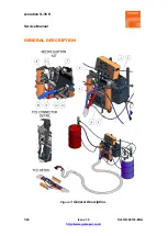
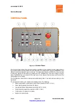
1.
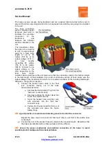
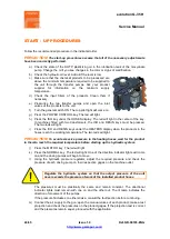
Main Power Switch
Turns the electric supply to the control panel on and off. It must be turned ON for any operation
to be performed with the unit. When turned ON, the green pilot at the top of the switch will come
on.
2.
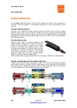
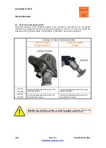
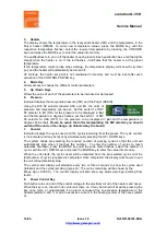
Hoses
The display shows the temperature of the Isocyanate hose
(ISO) and the temperature of the Polyol hose (RESIN).
The hose heating control may be automatic (optional) if using
a Temperature Control Sensor (TCS) or manual. The control
mode must be established with the two DIP selectors on the printed circuit board (S1).
If the TCS is located in the ISO hose (the recommended placement), then set the Isocyanate
DIP selector to ON and the Polyol DIP selector to OFF. In this setup, the Isocyanate
temperature will show on the indicator and the Polyol indicator will be blank. If the hose heat
system does not include a TCS or the sensor is inoperative, then set both DIP selectors to OFF.
In this setup, both temperature indicators will be blank. In the units equipped with two hose
transformer power, locate the DIP “Hose ISO” and the DIP “Hose RESIN” to ON position if the
hoses have TCS for the temperature control system, or OFF position if the hoses not have
TCS.
Please be aware that after manipulating the DIP selector you should switch off the unit so
the change. (in detected buy the board).
ISO on / RESIN off
w/TCS
ISO off / RESIN off
manual control
Dual Hose Heat
(optional)
To select the temperature when the unit is working in automatic control mode, press the MODE
key until the temperature flashes
,
select the required temperature by pressing the UP/DOWN
keys
and press the MODE key once more to enter the selected value into memory. Repeat the
process to select the Amps. When the unit is in automatic mode, the value of the power must
be set between 45 and 50 Amps.
Hose temperature settings that are higher than the temperature settings of the heaters cannot
be programmed.
If only one temperature control system is working (ISO or POL), the limiting temperature value
will be the highest set in the heaters.
If both temperature control systems are working (ISO and POL), the limiting value will be related
to each of their corresponding heaters.
Temperature settings are restricted to 80ºC maximum for hoses and 90ºC maximum for
heaters.


