


Revision 5
124
August 2021
8. Mount the new spectrometer on the mounting bracket. It should be oriented with the
USB port and serial number label facing forward. Reinstall and tighten fully all mounting
screws.
9. Remove the protective cap from the detector fibre optic cable and connect it to the
SMA connector on the top of the spectrometer. The nut only needs to be tightened to
hand tight.
10. Connect the trickle purge line to the purge port on the spectrometer’s left side.
11. Connect the USB cable to the USB port on the front of the spectrometer.
Once the new spectrometer has been installed in the analyzer, it will be necessary to install the
new spectrometer matrix file associated with the new spectrometer into the analyzer. Follow
the procedure below to update the spectrometer calibration matrix file.
1. Connect a laptop computer to the local Ethernet port. Ensure that the local Ethernet
connection displayed in the
Config
panel
Network
sub-panel displays as
Active
.
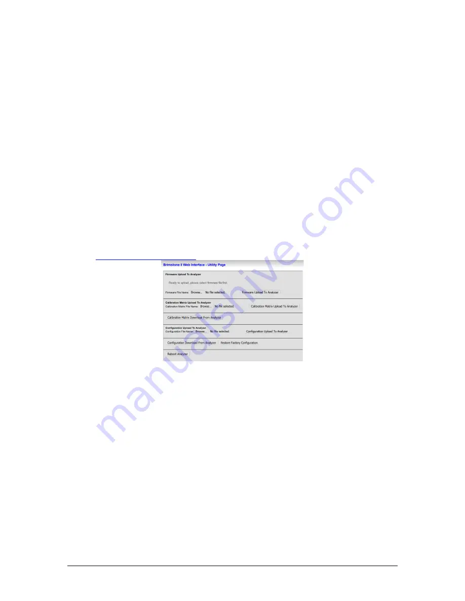
2. In a web browser program on the connected PC, enter in the IP address of the analyzer
followed by /Utility.html (for the local Ethernet port, this would be
http://192.9.200.16/Utility.html
) to access the
Utility
page shown in Figure 79.
Figure 79: Utility Page
3. Under the
Calibration Matrix Upload to Analyzer
heading, click on the
Browse
button.
Select the CSV format calibration matrix file with the file name indicated in the one-page
PDF document provided along with the spectrometer. The folder in which this file and the
calibration matrix will be found will have the spectrometer’s serial number (indicated on a
label on the front of the spectrometer) as the folder name. For an example, refer to Figure
80.
Summary of Contents for 943-TGXeNA
Page 130: ...Revision 5 130 August 2021 Figure 82 Oven Cabinet Door Removed ...
Page 131: ...Revision 5 131 August 2021 Figure 83 Control Cabinet Door Removed ...
Page 132: ...Revision 5 132 August 2021 Figure 84 Power Steam Air Signals Connection Details ...
Page 133: ...Revision 5 133 August 2021 Figure 85 AC Wiring Schematic ...
Page 134: ...Revision 5 134 August 2021 Figure 86 DC Signals and Wiring Diagram ...
Page 135: ...Revision 5 135 August 2021 Figure 87 Flow Diagram ...


