


© All rights reserved - Galmet Sp. z o.o. Sp. K.
Service and installation manual - C.H. Water Boiler
17
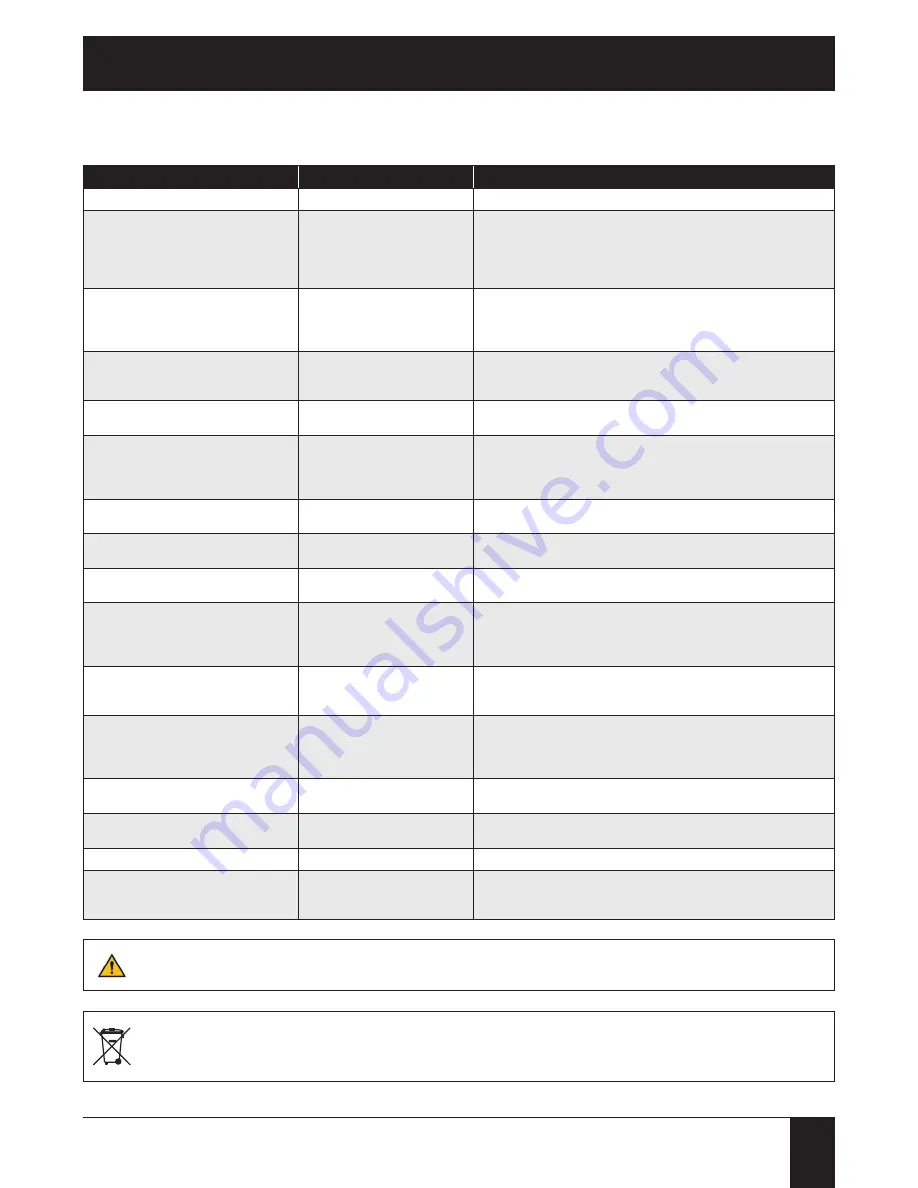
8. Troubleshooting
8. Troubleshooting
SHORTCOMINGS
CAUSE
CAUSE REMOVAL
FAILED LIGHTING UP
-
polluted burner
-
clean the burner combustion box of ash and slag
BOILER DOES NOT REACH SET TEMPERATURE
-
insufficient chimney draught
-
lack of incoming ventilation
-
polluted boiler
-
bad settings of boiler controller
-
poor quality of fuel
-
check chimney cleanness and size
-
make air inflow to boiler room
-
clean boiler exchanger
-
correct settings of boiler controller
-
change fuel
FUEL BURNS TOO QUICKLY
-
poor adjustment of air volume
-
excessive chimney draught
-
too little of fuel
-
diminish volume of supplied air
-
check chimney draught and size
-
reduce opening of air flow damper on flue
-
increase fuel dose
FUEL DOES NOT BURN COMPLETELY
-
poor adjustment of air volume
-
insufficient chimney draught
-
excessive fuel feeding
-
increase air volume
-
select air flow parameters- check chimney draught and size
-
correct settings of boiler controller
SLAG IS FORMED
-
excessive burning temperature
-
too low ash melting temperature
-
diminish volume of supplied air
-
change fuel
SMOKING FROM BOILER
-
polluted boiler
-
reduced opening of flue air damper
-
insufficient chimney draught
-
leaking seals
-
clean boiler exchanger
-
open air flow damper
-
check draught flow, possibly clean chimney duct
-
check door, flue and fuel bin cover seals and adjust their pressure
FEEDER DOES NOT FEED FUEL
-
broken overload safety breaker
-
feeder motor produces humming
-
determine the cause of breaking the breaker and replace it
-
replace the motor capacitor
BREAKING OF BREAKERS
-
screw claw burned out
-
slag coating in bend
-
exchange screw
-
clean bend
WATER LEAKAGE FROM BOILER
-
steam concentration on exchanger walls
-
untighten boiler body
-
may occur at first lighting up (increase temperature to 70°C)
-
contact service
TEMP. DROP IN THE BOILER
(THE PUMPS ARE WORKING, FAN AND FEEDER SHOWN
AS WORKING ON THE CONTROLLER'S DISPLAY)
-
activation of the STB system (boiler
temperature above 95°C)
-
push the button located on the boiler body under the protective cap (drawing 2 pos. 50)
-
check the operation of the CH and DHW pumps
-
check the operation of the 4-way valve
-
check if the boiler's power is selected correctly compared to the size of the heating circuit
TEMP. DROP IN THE BOILER
(THE PUMPS ARE WORKING, FAN AND FEEDER SHOWN
AS NOT WORKING ON THE CONTROLLER'S DISPLAY)
-
fuel bin cover opened
-
close the fuel bin cover
TEMP. DROP IN THE BOILER
(THE PUMPS ARE WORKING, FAN AND FEEDER SHOWN
AS WORKING ON THE CONTROLLER'S DISPLAY, NO
INCREASE OF EMBERS ON THE FURNACE)
-
no fuel in the fuel bin
-
boiler's power not high enough
-
refuel the fuel bin
-
increase the boiler's power
-
reduced the caloric value of the fuel
-
reduce the amount of air
CONTROLLER'S DISPLAY NOT WORKING, NO BACK-
LIGHT ON THE ON/OFF SWITCH
-
no power
-
check if the boiler is connected to the ~230V network
-
check the inclusion of the boiler room's fuse in the domestic fuse box
CONTROLLER'S DISPLAY NOT WORKING, BACKLIGHT
ON THE ON/OFF SWITCH, THE BOILER IS WORKING
-
no communication with the display
-
check the connection - SERVICE!
-
damaged display - SERVICE!
POWER OUTAGE
-
no power for up to 1 hour
-
when the power is restored the boiler will operate on previously set parameters
POWER OUTAGE
-
no power for more than 1 hour
-
when the power is restored the fan and the feeder will operate for 90 min trying to reignite
the embers, if after that time there will be no temperature increase the boiler will enter the
blanking mode: the fan and the feeder will be stopped, the pumps will continue to operate
Prior to calling for the service boiler exchanger should be thoroughly cleaned!
Crossed out symbol of a trash can means that after termination of product use in the area of the European Union it should be disposed of in a
special point dedicated for this purpose. It concerns both the device itself as well as the accessories marked with this symbol. These products
should not be disposed of with unsorted municipal wastes.


