GALA SYNERGIC 5000
20
3.10. RECOMMENDATIONS FOR THE USE OF THE EQUIPMENT AND WELDING OPERATION.
MATERIALS AND GASES.
The adjustment of the welding parameters in the MIG-MAG equipment is a much more sensitive job than
in traditional electrode welding equipment. The synergic control will permit easy regulation by informing the
control of the welding work you wish to carry out, the welding parameters will be automatically assigned.
The wire speed is synergically assigned (see section 3.4). Depending on the work you are carrying out you
can adjust it exactly to your needs using the wire-feed unit wire speed potentiometer. In general, bear in mind
the following considerations;
The welding intensity depends on the wire speed. If the wire speed increases, the welding current value will
increase resulting in a shorter arc. If you wish maximum penetration, you must weld at the minimum possible
voltage (selector switches V-U of the power source). Although it must be taken into account that as the voltage
drops, the aspect of the seam will worsen. The correct adjustment of the welding parameters leads to a gentle
and smooth development of the welding, with a typical sound during the operation. If the wire speed is high,
the wire tends to trip up and the arc becomes unstable. If the speed is low, there can be many splashes or the
wire can even burn.
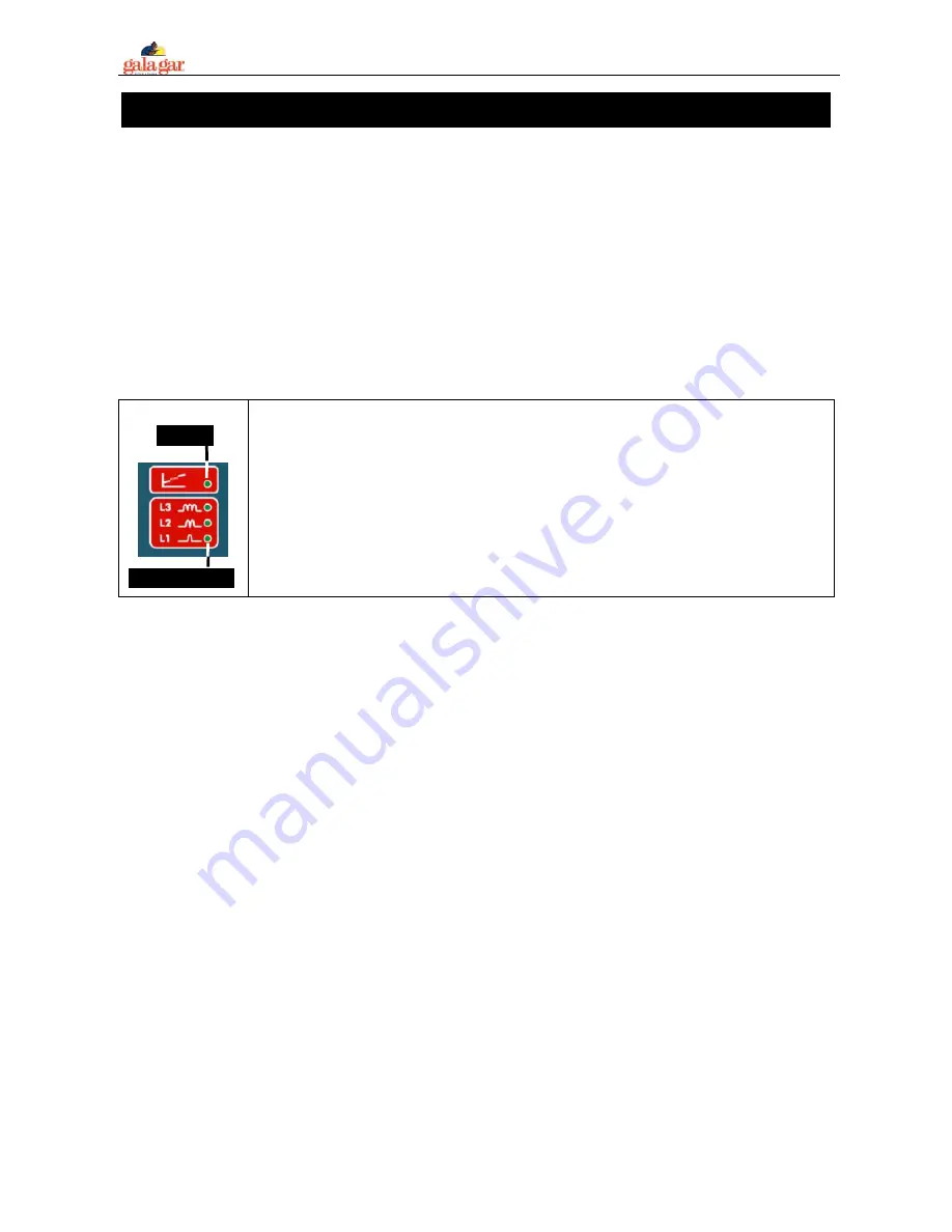
LD14-LD16
LD17
In synergic program, the control indicates the reactance intake to be used with Leds
LD13/LD14/LD15; if the reactance connected is lower than that indicated, there will be a
lot of splashes; if the reactance is higher, the wire will tend to get stuck.
IMPORTANT : Depending on the welding program and the welding power programmed,
the control system will tell us with the LD17 led if we are in globular transfer mode or
transition arc. These welding spots are characterised by an unstable arc with very thick
spots. Insofar as possible avoid this welding zone. The transition zone is situated
between the arc zone in short-circuit (lower power regulations) and the spray zone (higher
power regulations).
SOFT AND WEAKLY ALLOYED STEELS WELDING.
We recommend using a gas mixture of Argon + CO
2
(Fe-Ar + CO2 18% Program). Remember there are
special mixtures, which will optimise the welding process (SPECIAL program 04 Fe-Ar+CO2 5% +O5% )
Pure CO
2
can be used (SPECIAL program 03 Fe- CO2 100%), although we do not recommend this as,
although it provides greater welding penetration, the aspect of the welded seam is worse, and also the
number of projections is higher, the correct choice of the reactance tap acquiring great importance in this
case. The best gas flows are between 8 and 14 litres, depending on the wire diameter.
In this case the wire to be used will be SG 3/ SG 4 Si 1 type. Preserve the wire from humidity.
STAINLESS STEELS WELDING. CrNi –Ar CO
2
2% Program.
We advise using a mixture of Argon-CO
2
2-2.5%. The best gas flows are between 8 and 14 l/min. The
wire reel will be of stainless steel with composition Cr Ni 19-9.
ALUMINIUM WELDING. AlMg 5%-Ar Program / AlSi 5%-Ar Program.
The gas to be used in this case is pure Argon (MIG welding system). The flows will be between 8 and 18
l/min.
We advise using an aluminium wire with a minimum diameter of 1 mm. Aluminium is a soft material,
which can cause problems in driving. Follow the recommendations below:
-
The torch cable must be of Teflon. Torch neck: Strap cable. The torch length must be shortest possible
1÷ 3 m.
-
Remove the brass guide pipe of the wire-feed drive system. The Teflon towrope of torch must be
extended up to the driving rollers. Insert a drive roller with “U” type groove. Do not press the driving
motor handle too much.
If you wish to weld with aluminium and have doubts, contact us.


