Pub. 42004-392G
M
ODEL
LE200-RM
R
ACK
-M
OUNT
P
AGE
/P
ARTY
®
L
INE
E
XTENDER
P
AGE
54 of 56
e:\standard ioms - current release\42004 instr. manuals\42004-392g.doc
09/14
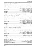
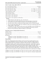
Contact Inputs (using optional I/O kit)
Dry contact input open resistance .................................................................................................
20,000
Dry contact input closed resistance ....................................................................................................
200
Wet contact input open voltage ........................................................................ 2.6
voltage
+3.6 volts dc
Wet contact input closed voltage ...................................................................... 0.0
voltage
0.23 volts dc
Contact input allowed voltage ......................................................................... 0.0
voltage
+3.6 volts dc
Contact input sink current ...........................................................................................................
1.0 mA dc
Contact input state duration ...............................................................................................................
50 ms
Contact input to contact output delay ................................................................................................
50 ms
Contact input to contact output jitter ..................................................................................................
10 ms
Contact input to contact output pulse width tolerance .......................................................................
10 ms
N
OTES
:
1.
Rapidly changing contact inputs may or may not be detected.
2.
Contact input to contact output specifications does not include the effects of relay bounce.
3.
The contact input’s negative terminal is tied directly to the LE200-RM’s signal ground.
4.
Wet contact input voltages are measured at the input terminals on the I/O Connection Module.
5.
The “wet contact input closed voltage” may be difficult to achieve when connecting a bipolar open
collector output to a contact input.
6.
A driving high wet contact input will source current to the LE200-RM when the LE200-RM is not
powered. This current may or may not prevent the LE200-RM from powering up properly.
7.
Be aware of the ground loop(s) formed when using wet contact inputs.
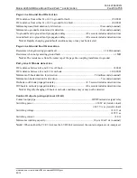
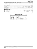
Fiber Optic Transceiver
(using optional transceiver)
Nominal Voltage ................................................................................................................................ 48 V dc
Maximum Current ............................................................................................................................. 500 mA
Optical Port Type ....................................................................................................................................... ST
Wavelength
GTRFP6972-102 chassis with GTRFP6972-201 transceiver ............................................. 1310 nm
GTRFP6972-102 chassis with GTRFP6972-202 transceiver ............................................. 1310 nm
Range dB (km)
N
OTE
: The maximum data transmission distance archived over
a
fiber optic link depends on many
factors, such as
Transmit
Power, Receiver Sensitivity / Saturation,
the
number of
fiber
connectors,
splices and
cable type.
Prior to designing or installing a fiber optic system, a loss budget analysis is
recommended to make certain the system will work over the proposed link. Both the passive and active
components of the circuit have to be included in the budget loss calculation. Passive loss is made up of
fiber loss, connector loss, and splice loss. Don't forget any couplers or splitters in the link. Active
components are system gain, wavelength, transmitter power, receiver sensitivity, and dynamic range. Prior
to system turn up, test the circuit with a source and FO power meter to ensure that it is within the loss
budget. The following distance information is approximate and
based on an overall power loss budget.
GTRFP6972-102 chassis with GTRFP6972-201 transceiver (62/125 µm cable) 12 dB power budget (5 km)
GTRFP6972-102 chassis with GTRFP6972-201 transceiver (9/125 µm cable) 31 dB power budget (80 km)

