


Pub. 42004-392G
M
ODEL
LE200-RM
R
ACK
-M
OUNT
P
AGE
/P
ARTY
®
L
INE
E
XTENDER
P
AGE
24 of 56
e:\standard ioms - current release\42004 instr. manuals\42004-392g.doc
09/14
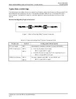
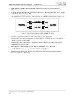
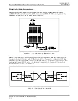
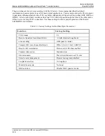
Point to Multi-point Page/Party
®
System Connection
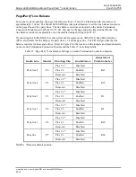
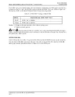
Figure 8. Point to Multi-point Page/Party
®
System Connection
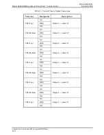
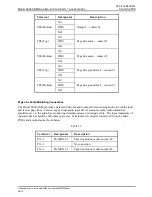
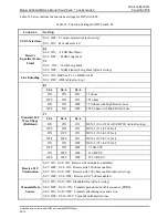
Table 25. Point to Multi-point Page/Party
®
System Connection Table
Parameter Switch
Configuration
Description
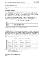
T1 Line Length SW2
Determined by installation distance between each pair of Line Extenders:
A to D
B to E
C to F
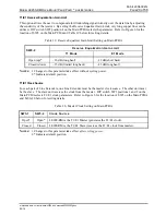
T1/E1 Clock
Source
SW3-1
SW3-2
Units A, B, and C are the master T1/E1 clock sources:
SW3-1 (open) SW3-2 (open)
Unit D is a slave and uses the T1/E1 clock from Unit A:
SW3-1 (closed) SW3-2 (closed)
Unit E is a slave and uses the T1/E1 clock from Unit B:
SW3-1 (closed) SW3-2 (closed)
Unit F is a slave and uses the T1/E1 clock from Unit C:
SW3-1 (closed) SW3-2 (closed)
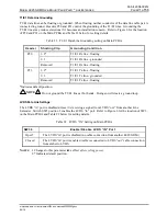
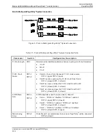
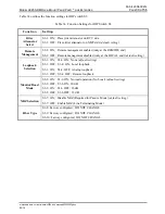
LVDS Data
Line
SW3-3
SW3-4
LVDS data link is used between units A, B and C.
Unit A - “LVDS in” disabled, “LVDS out” enabled:
SW3-3 (open) SW3-4 (closed)
Unit B - “LVDS in” enabled, “LVDS out” enabled:
SW3-3 (closed) SW3-4 (closed)
Unit C - “LVDS in ” enabled, “LVDS out” disabled:
SW3-3 (closed) SW3-4 (open)
Mute Analog
Lines
SW6-4
Units B and C are muted since there is not a Page/Party
®
cable connected:
SW6-4
(closed)