

Pub. 42004-392G
M
ODEL
LE200-RM
R
ACK
-M
OUNT
P
AGE
/P
ARTY
®
L
INE
E
XTENDER
P
AGE
30 of 56
e:\standard ioms - current release\42004 instr. manuals\42004-392g.doc
09/14
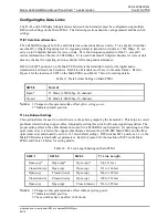
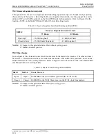
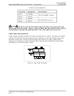
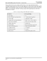
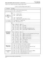
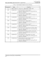
Table 28. Terminal Block P19
Terminal Designator Description
P19-1 TX
Ring
Data TRANSMIT wire pair
P19-2 TX
Tip
P19-3 RX
Ring
Data RECEIVE wire pair
P19-4 RX
Tip
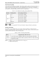
NOTE
Do NOT connect the TX (transmit) signal to the RX (receive) signal on the same
Model LE200-RM Line Extender. Doing so creates a feedback path that usually results in extremely
loud oscillations on the page line and the party lines. The contact outputs may also activate.
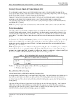
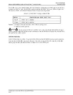
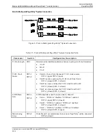
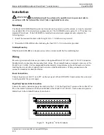
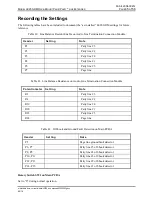
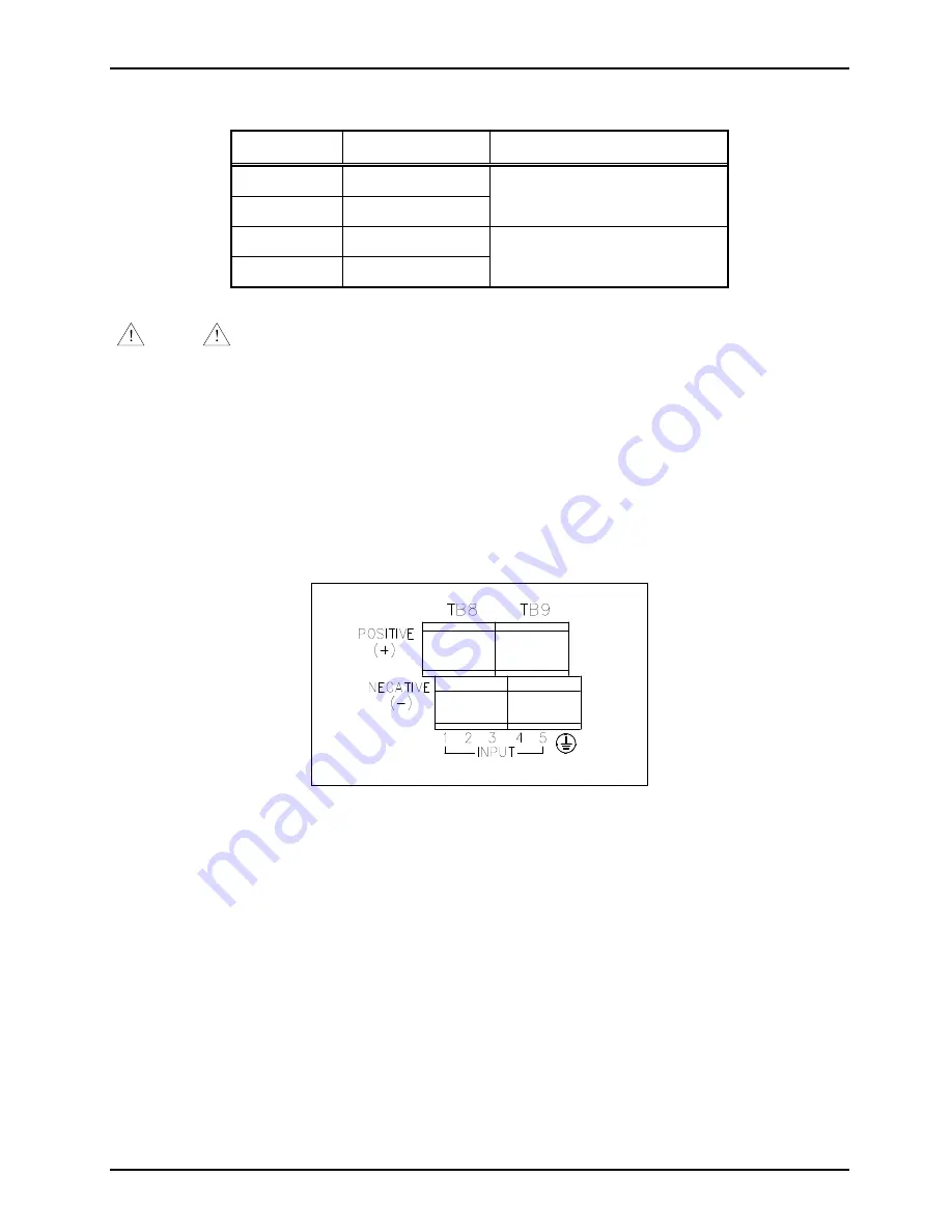
Contact Closure Input Connections
Contact inputs are typically connected to switches or mechanical relay contacts. Five inputs are available
on Model 12118-012 Kit with each input requiring two conductors. Connect the normally open contact
across the top and bottom. If using a solid state switch as the input device, observe polarity of the
connection (
−
) on bottom, (+) on top. Each input cable connection point is labeled next to the terminal
block TB8 and 9 as shown in Figure 15 below.
Figure 15. Input Contact Terminals