


Pub. 42004-392G
M
ODEL
LE200-RM
R
ACK
-M
OUNT
P
AGE
/P
ARTY
®
L
INE
E
XTENDER
P
AGE
3 of 56
e:\standard ioms - current release\42004 instr. manuals\42004-392g.doc
09/14
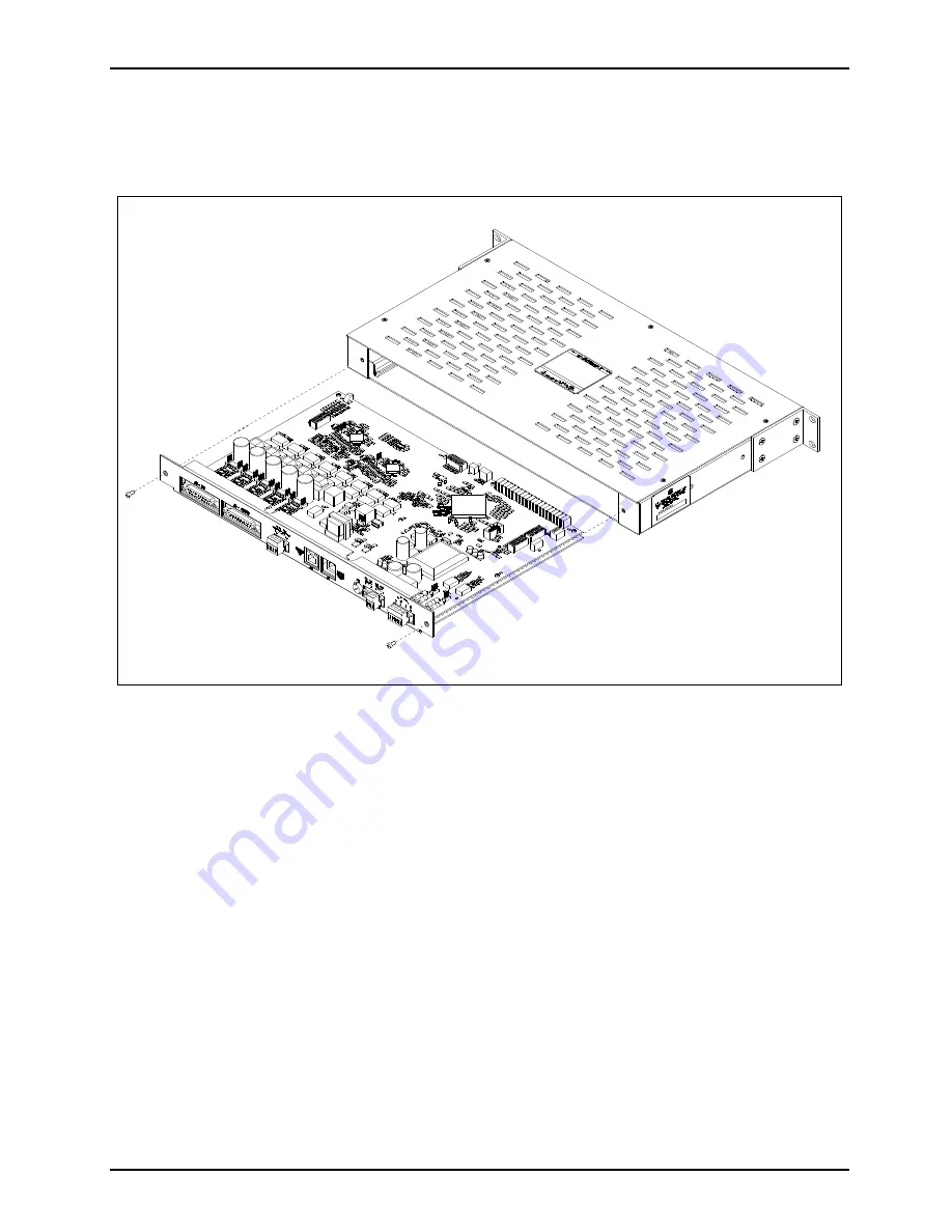
PCBA Access
The Main PCBA can be easily accessed to set up switches and jumpers. Remove the two #6-32 screws
from the rear of the unit. Slide the PCBA support plate and PCBA out of the unit. See Figure 3.
Figure 3. Access to the Model LE200-RM Line Extender’s Main PCBA