MCTB
81
The advantage of cascade control, like in the example above, comes down to isolating a process with relatively
slow dynamics (like temperature, level, humidity) from some other relatively-fast process that has to be
manipulated to control the slow process. If the heating elements were directly immersed in the product, then
cascade control would most likely not be necessary as the heating elements would directly affect the product
temperature. Since the heating element affects oil temperature, and that in turn affects product temperature,
cascade control is necessary in order to properly control the system.
Cascade control does have disadvantages. One, it requires an additional measurement in order to work. Two,
there is an additional controller that has to be tuned. And three, the control strategy is more complex, for
engineers and operators alike. These disadvantages have to be weighed up against the benefits of the
expected improvement in control to decide if cascade control should be implemented.
Cascade control is beneficial only if the dynamics of the inner loop are fast compared to those of the outer loop.
Cascade control should generally only be used if the inner loop is at least three times faster than the outer loop,
because the improved performance may not justify the added complexity. In addition to the diminished benefits
of cascade control when the inner loop is not significantly faster than the outer loop, there is also a risk of
interaction between the two loops that could result in instability. This is especially true if the inner loop is tuned
very aggressively.
4.7.2
Cascade Settings
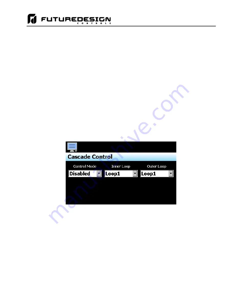
The Cascade Control screen is accessed from the Options menu. The function selections are provided via
three, drop down menus. These menus allow the mode of operation to be set as well as select which loops are
to be the inner and outer.
The
Cascade Control Mode
drop down menu provides the following selections:
Disabled
Cascade control is not implemented and all loops run independently of one another.
Process
This mode allows the lower and upper set point range of the inner loop to be defined relative
to the outer loop’s percentage of output. When selected, entry fields (on the Cascade screen
in the runtime application) are provided and used to set the lower and upper set point range of
the inner loop. The output of the primary loop is used to calculate a linear set point between
these lower and upper values in order to generate the set point for the inner loop.
For example, if the outer loop is configured for heat only or cool only, it will have an output of
0 to 100%. If the lower and upper limits entered in the runtime on the Cascade screen are 0
and 50, an output of 0 to 100% on the outer loop will generate a set point of 0 to 50 on the inner
loop. So, an output of 50% would be a set point of 25 on the inner loop.
Summary of Contents for MCTB 4.3
Page 24: ...MCTB 24...
Page 195: ...MCTB 195...
Page 227: ...MCTB 227 A 5 SmartIO Monitor Module Specifications...
Page 228: ...MCTB 228 A 6 Expansion IO Module Specifications...
Page 229: ...MCTB 229 A 7 Power Supply Specifications DIN Rail Mount Power Supply Specifications...
Page 230: ...MCTB 230...
Page 231: ...MCTB 231 Open Frame Power Supply Specifications...
Page 232: ...MCTB 232...
Page 233: ...MCTB 233 A 8 Power On Delay Relay Specifications GE1A C10HA110...
Page 234: ...MCTB 234...


