1. INSTALLATION
1-6
• Make sure there are no objects near the vent.
• Leave enough space around the unit for maintenance and servicing. The recom-
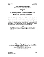
mended maintenance space appears in the outline drawing at the back of this manual.
• Observe the compass safe distances shown in the safety instructions on page i to pre-
vent interference to a magnetic compass.
Install the unit as follows:
Tabletop:
Fasten with four self-tapping screws.
Bulkhead:
Screw in two self-tapping screws for the upper side. Leave approximately 5
mm of the screws exposed. Hang unit on screws and tighten screws. Screw in two self-
tapping screws for lower side and tighten.
259(10.2")
90(3.54")
#85(3.34")
CABLE INLET
144
±
1(56.7"
±
0.03")
219(8.62")
VENT
#70(2.75")
255(10.0")
230
±
1
(9.06"
±
0.03")
EARTH
TERMINAL
(FIXING
HOLE)
2-
φ
5
(0.2")
44
(1.73")
12(0.47")
R6(0.24")
#70(2.75")
Summary of Contents for NAVpilot-700
Page 8: ...vi This page intentionally left blank ...
Page 22: ...1 INSTALLATION 1 14 This page is intentionally left blank ...
Page 74: ...3 INITIAL SETTINGS 3 38 This page is intentionally left blank ...
Page 80: ...24 Nov 09 R Esumi D 1 ...
Page 81: ...24 Nov 09 R Esumi D 2 ...
Page 82: ...24 Nov 09 R Esumi D 3 ...
Page 83: ...24 Nov 09 R Esumi D 4 ...
Page 84: ...24 Nov 09 R Esumi D 5 ...
Page 85: ...24 Nov 09 R Esumi D 6 ...
Page 86: ...24 Nov 09 R Esumi D 7 ...
Page 87: ...24 Nov 09 R Esumi ...
Page 88: ......
Page 89: ...Y Hatai D 10 ...
Page 90: ......
Page 91: ......
Page 92: ......
Page 93: ......
Page 94: ......
Page 95: ...25 Jan 10 R Esumi ...