


Power up
4-2
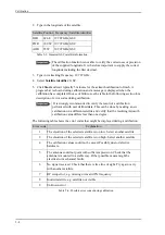
The LEDs
Power
and
Fail/Pass
are
steady green
, the LED Logon is off. For further
information on status indicators see
Status signalling with LEDs and status messages
on page 7-15.
Make sure there are no hardware failures or error codes present, check the display of
the ACU for events. For more information on error codes and events see
System
messages
on page B-1.
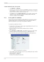
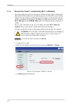
3. Make an azimuth and a cable loss calibration, see
Calibration
on page 5-7.
4. Switch on the GMU.
For more detailed step-by-step instructions, see the chapter
Configuration
on page 5-1.
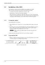
4.2.3
Initialisation steps in daily use
Once the system is configured and a satellite profile is active, the startup sequence is as
follows:
• ACU POST
• Antenna Initializing
• Antenna SW upload (If the software versions in the ADU and ACU are not the
same, a software update is done during startup.)
• Antenna POST
• READY
• POINTING ANTENNA
• ACQUIRING SIGNAL
• TRACKING
4.2.4
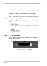
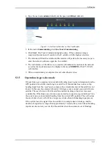
FV-110GX operational
When the display shows
TRACKING
.
MDM: NETOK
and the LED
Logon
is steady
green the system is operational.
Figure 4-3: ACU display, system operational
0DLQ1$9*+0'01(72./$1±
75$&.,1*
6$7:5;/+7;0$5
Summary of Contents for FV-110GX
Page 1: ...GX TERMINAL FV 110GX OPERATOR S MANUAL www furuno com Model ...
Page 16: ...xiv This page is intentionally left blank ...
Page 46: ...Installation of the ADU 2 22 N connector interface on the ADU ...
Page 54: ...To connect the ADU ACU and GMU 2 30 This page is intentionally left blank ...
Page 110: ...Installation check list Functional test in harbor 6 4 This page is intentionally left blank ...
Page 164: ...Supported commands C 10 This page is intentionally left blank ...
Page 165: ...D 1 Appendix D Approvals D This appendix lists the approvals for FV 110GX OEM declaration ...
Page 166: ...OEM declaration D 2 D 1 OEM declaration ...
Page 173: ...OD 1 30 Jul 2018 H MAKI ...
Page 174: ...OD 2 30 Jul 2018 H MAKI ...
Page 175: ...OD 3 2 Oct 2018 H MAKI ...
Page 176: ...OD 4 2 Oct 2018 H MAKI ...
Page 178: ......
Page 186: ......


