


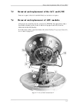
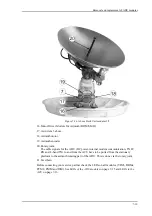


Removal and replacement of ADU modules
7-18
1. GNSS module.
2. VSAT Interface Module (VIM3).
3. Pedestal Control Module (PCM2).
4. Service switch.
In switch-off position the Motor Driver modules (DDM/SMD), the Polarisation Motor
Module (PMM) and the BUC are turned off for safe conditions during service and
repair. The switch must be in on position for normal ADU operation.
5. Motor Driver modules (DDM/SMD).
6. Cross elevation motor and encoder.
7. Zero Reference Module (x3) (ZRM) (not visible on photo). (2 in the figure above, i in
the figure below.
8. Motor Driver Module for elevation (on the bottom side) (DDM/SMD).
9. Elevation motor and encoder (not visible).
10.BUC Control Module (BCM).
11.Block Up Converter (BUC). (behind cable screen, not visible on photo)
12.Low Noise Block down converter.
13.Polariser.
14.Inertial Sensor Module (ISM).
15.Elevation locking pin to lock the antenna dish in a fixed position (for safety during
service) (not visible on photo).
Summary of Contents for FV-110GX
Page 1: ...GX TERMINAL FV 110GX OPERATOR S MANUAL www furuno com Model ...
Page 16: ...xiv This page is intentionally left blank ...
Page 46: ...Installation of the ADU 2 22 N connector interface on the ADU ...
Page 54: ...To connect the ADU ACU and GMU 2 30 This page is intentionally left blank ...
Page 110: ...Installation check list Functional test in harbor 6 4 This page is intentionally left blank ...
Page 164: ...Supported commands C 10 This page is intentionally left blank ...
Page 165: ...D 1 Appendix D Approvals D This appendix lists the approvals for FV 110GX OEM declaration ...
Page 166: ...OEM declaration D 2 D 1 OEM declaration ...
Page 173: ...OD 1 30 Jul 2018 H MAKI ...
Page 174: ...OD 2 30 Jul 2018 H MAKI ...
Page 175: ...OD 3 2 Oct 2018 H MAKI ...
Page 176: ...OD 4 2 Oct 2018 H MAKI ...
Page 178: ......
Page 186: ......


