Funk-Electronic Piciorgros RTU-81 User Manual Download Page 49

Funk-Electronic Piciorgros GmbH  

RTU-810


V2.30 - Page 49  of   126 


3.2.6


RSSI monitor 

The RSSI monitor acts as a network monitor and gives a 
complete overview over the radio network. Even more, it lists 
every station it can receive which is using the same radio 
layer address. 
 
This gives also a feedback about station in neighbor radio 
networks on the same frequency to see possible interferences 
if the networks are running in continuous operation or to 
determine if a station in a neighbor network can be used as a 
radio repeater for the own network if time slot operation is 
used. 
 
For clarification: Any RTU-810 can only receive and "see" 
other Piciorgros devices if they are delivered to the same 
customer. It is not possible to monitor devices from other 
customers on the same frequency or to communicate with 

them. The RSSI monitor will not list any "alien" devices outside the own radio 
networks. 


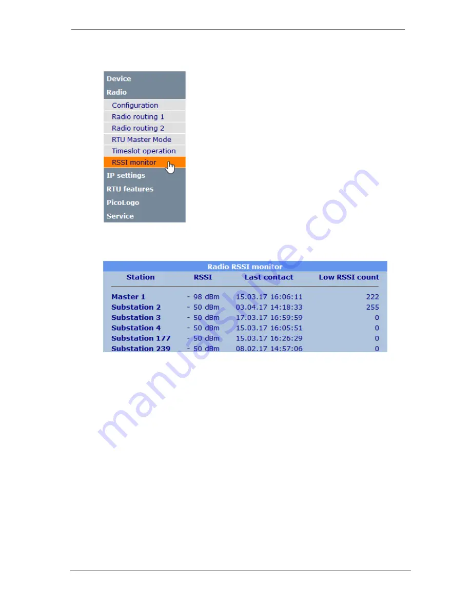
The RSSI monitor lists each station it has ever seen in a list, started with master stations 
and followed with slave (sub) stations, ordered by radio address. 
 
The time stamp of the last received data from the particular station is stored along with 
the RSSI value of the reception. A threshold value can be defined, and any data which is 
received with a lower field strength as the defined threshold will count up the "Low 
RSSI count". This can be used to check whether the receive field strength of a station 
drops below a certain value from time to time. 
 

Note:

 Old TRM-700/710 master radios can use a master address 0, although this 

address is not valid anymore in newer devices. For that reason a "Master 0" can appear 
in the list! 


Summary of Contents for RTU-81

Page 1: ...TRM 810 RTU 810 RTU 81 User Guide Funk Electronic Piciorgros GmbH Claudiastrasse 5 51149 Cologne Germany...

Page 2: ...3 Ethernet Interface 16 2 2 4 Extension Port for additional I O modules only devices with embedded I O 16 2 2 5 Connecting the I O RTU 810 DAx types only 17 2 2 6 Connecting the Antenna 20 2 3 LED Fun...

Page 3: ...93 4 1 1 Tunneling a serial connection with the SIG 810 Q2 3 2017 93 4 1 2 Operating modes 94 4 1 3 Address detection and routing 95 4 1 4 Configuring the IP link 96 4 1 5 IP link status information 9...

Page 4: ...mands 112 6 2 Accessing the I O using the IEC60870 protocol Future option 113 6 2 1 Native internal IEC60870 support for the basic I O s 113 7 PICOLOGO USER APPLICATION INTERFACE 114 8 TROUBLESHOOTING...

Page 5: ...should be taken to ensure that the radio and antenna systems are installed and commissioned only by trained persons This radio equipment should not be used in life support systems or in safety systems...

Page 6: ...4 MHz with a transmit power of up to 10mW It also has only a fixed internal I O setup of 8 binary inputs 8 binary outputs and 2 analog inputs Apart from this it has the same features as the RTU 810 In...

Page 7: ...10 DA3 Radio modem with two serial ports one Ethernet port 16DI 16DO no embedded AI and an expansion port connector for PEM type expansion modules with additional I O RTU 810 DA4 Radio modem with two...

Page 8: ...RTU 810 V2 30 Page 8 of 126 By default the RTU 810 will be delivered with two serial RS 232 ports RS 422 or RS 485 are options which must be provided with the order They can t be activated or changed...

Page 9: ...ace The PicoLogo option is a powerful User Application Interface that can be used similar to a Micro PLC to generate Alarms Text Messages M2M Communication or to monitor and supervise digital or analo...

Page 10: ...available in short or mid term These features are described in blue paragraphs Related hardware devices and hardware options will be GSM LTE option for the RTU 810 SIG 810 Serial to IP Gateway for tun...

Page 11: ...V2 30 Page 11 of 126 1 9 Document Changes The history of this documentation is listed below Firmware Version Document Version Comments Changes 2 30 2 30 Initial Document Release Software Release Notes...

Page 12: ...provided to connect PEM I O expansion modules Also on the upper side of the unit the plug in terminal connector for the power supply 12 24 VDC 20 and a BNC socket for the antenna can be found RTU 810...

Page 13: ...lted downward slightly The Module is then pushed upward 1 and rotated backward 2 until the upper lip of the clip snaps onto the upper flange of the DIN rail 2 1 3 Dismounting To dismount the Module fo...

Page 14: ...nnected through 3 way screw terminal connector located on the upper side of the enclosure The terminals are assigned as follows viewed from the front of the module facing the front panel Outer left En...

Page 15: ...ng is 9600 bps 8 data bits no parity 1 stop bit If a frame error is detected or if the parity bit does not conform to the setting the received data block is rejected Pin No Pin Assignment RS 232 2 TxD...

Page 16: ...xtension Port for additional I O modules only devices with embedded I O The I O expansion connector is located at the upper right part of the RTU 810 of all TMO versions with embedded I O The connecto...

Page 17: ...nal If the C terminal is connected to the ground the inputs will be active if the positive voltage 12 14V applies If the C terminal is connected to the positive voltage the inputs are activated by app...

Page 18: ...supply must be provided externally in the loop The input range is 0 20mA with a resolution of 12 bit Analog outputs DA4 DA5 type The analog outputs are an active source for 0 20mA which means that i e...

Page 19: ...Funk Electronic Piciorgros GmbH RTU 810 V2 30 Page 19 of 126 2 2 6 Connection diagram RTU 81...

Page 20: ...requency The antenna cable 50 ohm should not be longer than 5 meters and should be good quality low loss type RG 213 or Aircell Overvoltage protection suitable for protecting the modem is available Th...

Page 21: ...e 21 of 126 2 3 LED Functions Groups of LED lamps on the front panel of the RTU 810 indicate the operating condition of the modem the field strength of the received radio signal and error conditions i...

Page 22: ...RTU 810 sends data via the COM interface COM Rx Lights up while the RTU 810 receives data via the COM interface AUX Tx Lights up while the RTU 810 sends data via the AUX interface AUX Tx Lights up whi...

Page 23: ...S 100 time server Permanently on The time synchronization is up to date and time slot operation can be used Mostly off with an on blip every second DCF PTS 100 only The RTU 810 is waiting for the seco...

Page 24: ...ils MSG If the RTU 810 has a GSM option this LED lights up if a SMS is being transmitted or received GSM If the RTU 810 has a GSM option this LED shows the registration status of the GSM module Slow 1...

Page 25: ...168 0 199 20 regardless of the configured Ethernet IP address Long flash short flash alternating The device is processing or performing a firmware update 4 blinks then pause The internal radio module...

Page 26: ...l then perform a reset to factory defaults 2 5 Temporary reset to default IP address If the IP address of a RTU 810 is unknown it can be temporarily reset to the default address Press for one second o...

Page 27: ...0 0 If the IP address of the RTU 810 is typed into the web browser the login page will appear The first login will be done using the default username and password take care as both are case sensitive...

Page 28: ...Funk Electronic Piciorgros GmbH RTU 810 V2 30 Page 28 of 126 After 5 minutes without activity the user will be automatically logged out...

Page 29: ...ctronic Piciorgros GmbH RTU 810 V2 30 Page 29 of 126 3 1 1 Navigation using the Menu To select a menu move the cursor over the desired headword and click it Then the menu will open displaying the next...

Page 30: ...s which have been transmitted initially Note that a Reset will not work after the changes have been applied Note Instead of clicking Apply pressing the Enter key will have the same function on most pa...

Page 31: ...An easy way to continue the configuration session is to reload the page by hitting the F5 key 3 1 5 Recommended Web Browsers For the configuration of the RTU 810 these Browsers are recommended Mozilla...

Page 32: ...3 2 Radio configuration This section explains the radio configuration of the RTU 810 Most important thing to start with is to set the correct radio frequency and transmit power 3 2 1 Configuration The...

Page 33: ...n t send or transmit data to the own radio network This radio layer address is displayed here It is a 4 digit hexadecimal number Variable address A customer can apply for a radio layer address range i...

Page 34: ...the hardware is listed below this field The frequency must be a multiple of 12 5 kHz If this is not the case the entered frequency will be automatically corrected when the page is applied Output power...

Page 35: ...he own radio among the general RSSI of the data traffic on this frequency Peak hold expire If for this amount of minutes no access to the RTU 810 has occurred the peak hold LED will start to flash A f...

Page 36: ...ted Value instead of a calibrated dBm value The device ID will not be 0x0800 to indicate it s an RTU 810 it s instead reporting the old ID from the 710 series RTU 810 DA1 0x0011 RTU 710 DA1 RTU 810 DA...

Page 37: ...RTU master mode is used to achieve point to point or point to multipoint connections the routing table which should be used can be directly selected for each slave For the serial master modes the used...

Page 38: ...would be Data which should be sent to slave address 1 will take this route RTU 810 slave addr 2 slave addr 7 slave addr 1 Data which should be sent to slave address 2 will take this route RTU 810 sla...

Page 39: ...are configured to the particular failed slave will be switched to OFF The digital and analog outputs of the respective slave are also written to OFF by the RTU 810 master If the radio link to the sla...

Page 40: ...g polled itself it will set its outputs to OFF state 0 disables the X timeout at the slaves Delay after each station polling If this value is greater than 0 the RTU 810 will wait this number of second...

Page 41: ...nsmitted from the master RTU 810 to the remote slave Routing table Determines which radio routing table should be used to route the radio telegrams to the particular slave This will be changed from so...

Page 42: ...s on port A0 A3 of the slave 1 will now be transferred to the outputs C0 C3 of the master RTU 810 At the same time the valid range for the same parameter on the following slaves have been updated The...

Page 43: ...at once it ll be possible to enter more I O in total as are available on the master RTU 810 In this case after pressing Apply an error message will indicate this fact on the page The communication to...

Page 44: ...CADA routing tables with its IP entry do have the ability to specify an IP address beside the radio slave address In the slave configuration a selection for each slave will be added to configure wheth...

Page 45: ...able information about the slave like available physical I O etc The slave will be automatically set to the same family address as the master and will have a slave address automatically assigned Final...

Page 46: ...ronic Piciorgros GmbH RTU 810 V2 30 Page 46 of 126 The automatically configured setup will be available in the RTU Master Mode configuration page afterwards It can be modified and fine tuned anytime a...

Page 47: ...connection to the RTU 810 is a DCF 77 coded signal hence it requires the DCF or PTS option at the RTU 810 DCF 77 The DCF option is a hardware option and includes a socket for an active DCF 77 antenna...

Page 48: ...t configuration This selects any of the 10 available time slots for radio operation If all time slots are set to off the RTU 810 operates in continuous operation Each 6 seconds time slot can be furthe...

Page 49: ...not possible to monitor devices from other customers on the same frequency or to communicate with them The RSSI monitor will not list any alien devices outside the own radio networks The RSSI monitor...

Page 50: ...can be used to set the threshold for the Low RSSI counts in a range between 60 and 140 dBm Note Clicking Apply on this page will reset all collected statistics If the RSSi monitor values just should...

Page 51: ...be used to identify the device It can also be used as a placeholder in PicoLogo TextSend blocks PicoLogo state State of the internal PicoLogo application This can be Stopped Running or Error Parse for...

Page 52: ...face The settings of the COM and AUX serial interfaces are identical therefore both are described in this chapter Both interfaces can operate completely separated from each other so two different serv...

Page 53: ...data via the serial interface is treated as MODBUS RTU data The RTU 810 will answer them locally if a MODBUS RTU telegram addressed to the local MODBUS address of the RTU 810 is seen on the interface...

Page 54: ...ace will use the IP address which is determined from the selected SCADA routing table If the IP address is 0 0 0 0 no data will be sent In Mixed mode the slaves can be partially in the radio network a...

Page 55: ...col will run on the particular interface Communication protocol used on COM AUX Selects a known SCADA protocol User defined protocol gives the ability to define the position and format of the address...

Page 56: ...But any number of bits between 1 and 32 will work here in case the address is only a part of a byte or a word Offset address bit In case the address does not start with bit 0 LSB of a byte an offset t...

Page 57: ...ble to determine the radio slave address to which the data should be sent This option can be used to override these mechanisms If all fields are set to 0 the protocol extraction routing tables are use...

Page 58: ...al parameter settings This configures the serial parameters for the serial interface Baudrate The baud rate of the interface in the range between 300 and 57600 bit s Databit The number of data bits pe...

Page 59: ...transparent communication Once the first character is received on the interface a timer is set counting down milliseconds With each character which is received before this timer runs out the characte...

Page 60: ...application interface is to name it as a serial interface but with a different physics It can i e be used to use an IP LAN network where otherwise a very long serial cable would be needed to connect t...

Page 61: ...ly the listening port must be defined further down TCP client The interface will act as a TCP client and opens a TCP connection to a given IP address and port If the connection can t be established th...

Page 62: ...on of the Radio addr and IP address fields are optional By default the SCADA addresses 1 239 are preset with radio slave addresses 1 239 all other fields are set to 0 3 3 4 1 Browse page As only 10 20...

Page 63: ...logical address is set to a certain value the ID number is the result of the extracted SCADA address minus the value of the first logical address field in the interface IP address IP address of the s...

Page 64: ...able reset option When CLR is types in this field and then Apply is clicked the SCADA routing table will be restored to default state This means a 1 1 routing for SCADA addresses 1 239 to radio slave...

Page 65: ...he port needs a device restart MODBUS IP Active Turns the MODBUS IP function On or Off A change needs a device restart MODBUS IP protocol Selects the use of UDP or TCP for the MODBUS IP access Default...

Page 66: ...6 1 Internal clock Date The current date in format DD MM YYYY To set the date to a different value the data can be entered in these fields Internal time Current time in 24h format It requires a page r...

Page 67: ...e internal real time clock and the internal time slot synchronization This method is eligible as a clock source for time slot operation mode SNTP server IP The IP address of the SNTP time server This...

Page 68: ...nternet or should access the internet or other devices in the LAN by itself using a router In this case the IP address of the router must be entered here The standard gateway must be in the same IP su...

Page 69: ...the email address which is used in the From field of the email and in the email envelope during transmission to the email server AUTH username This is the username which is used for SMTP authenticatio...

Page 70: ...up The RTU 810 can send logger messages and events to a SYSLOG server via the SNMP trap protocol It does not support management by SNMP Messages are sent via UDP to port 162 of the given syslog server...

Page 71: ...serial master mode ZZTR ZZTRM can be used If the RTU 810 receives a ZZTR telegram it will check if this is a MODBUS RTU datagram when this option is turned on If the MODBUS address is matching the RT...

Page 72: ...y connected equipment will write into these registers Local equipment can read write these registers from MODBUS address 650 689 For remote equipment these will be seen as common analog inputs The vir...

Page 73: ...or a MDP 310 200 can change if the number of available I O is changing I e the virtual analog outputs will shift back to a different register address if an expansion module with analog outputs is add...

Page 74: ...TU 810 s start and each time the RTU 810 is accessed by a master regardless which protocol the access is using DNP3 IEC 60870 MODBUS and regardless of the interface which was used radio GSM Ethernet s...

Page 75: ...ry inputs Inputs provided by expansion modules do not provide advanced functions 3 5 2 1 Browse page As only 10 entries are displayed per page but the configuration table holds a maximum of 16 entries...

Page 76: ...time unit is 100ms This function can be used to suppress glitches Any delays configured here will be applied before any other processing functions like SCADA queries or PicoLogo Num Number of the inpu...

Page 77: ...he maximum frequency is 10 Hz This can be used as a pulse counter Configured as a time counter the counting register will be increased by 1 in every second the input is active Resolution is 100ms The...

Page 78: ...N mode This switch is non volatile and the setting is preserved during a power down of the RTU 810 3 6 1 2 PicoLogo status This section indicates the status of the PicoLogo application STOPPED No Pico...

Page 79: ...al the run time version in the RTU 810 Device ID The device ID of the RTU 810 ID of program The device ID for which the application was compiled Program name The name which was used to store the appli...

Page 80: ...orgros GmbH RTU 810 V2 30 Page 80 of 126 3 6 1 4 Erase program A loaded PicoLogo application can be erased here For security reasons the word Delete must be typed into the text field and Apply must be...

Page 81: ...ition these addresses can be viewed and edited in the contact table 3 6 2 1 Browse page As only 10 entries are displayed per page but the contact holds a maximum of 50 entries the start index of each...

Page 82: ...r contact is opened To make destination addresses for messages easily changeable without recompiling the whole application in the PicoLogo editor addresses are listed in the contact table The applicat...

Page 83: ...for an easy on the fly change 3 6 3 1 Browse page As only 10 entries are displayed per page but the parameters section can hold more entries the start index of each page can be entered here A click o...

Page 84: ...an be put into the web server for easy reviewing and changing In this case the checkbox Description visible in web server must be checked for the constants in the PicoLogo block as done in the applica...

Page 85: ...is the contact information of Piciorgros GmbH After login the RTU 810 web server comes up with this page 3 7 2 Manage password This changes the password of the current logged in user The password must...

Page 86: ...bH RTU 810 V2 30 Page 86 of 126 3 7 3 Configuration This page allows some configuration for the Protocol Logger Event logger can show the status of the additional RTU 810 features and can be used to e...

Page 87: ...res up to 650 events like communications failures for the RTU master mode device restarts and much more The entries are nonvolatile and survive power downs If 650 entries are stored each new entry wil...

Page 88: ...an have this status announced Enabled The feature is permanently enabled and can be used Temporary This feature is in trial mode for a certain time The remaining time is also listed After the remainin...

Page 89: ...or which it was ordered In this example an activation key is purchased to turn the serial master mode activation into a permanent one and to activate the RTU master mode feature This is the situation...

Page 90: ...to reset if to factory default Restart A click on this button restarts the RTU 810 Reset to factory default A click on this button does a full reset to factory defaults Any customer settings are erase...

Page 91: ...The register addresses are identical to the MODBUS register addresses therefore it can be used to check the content of the I O registers Also in a support case you might be asked to read out certain...

Page 92: ...The event logger stores events and exceptions communication failures in RTU master mode and much more This is the first point to check if the communication to a RTU 810 was disturbed or if other prob...

Page 93: ...es All IP data must be addressed to the RTU 810 as the IP connection is just locally To route the data to different destinations in the radio network the known mechanism of address detection and the u...

Page 94: ...4 of 126 4 1 2 Operating modes The operating modes available for the IP Application Interface are exactly the same as for the serial ports they are not described here again in detail For a detailed de...

Page 95: ...inside the data payload received on the interface This may be common and known serial SCADA protocols which are embedded in the IP packet to the RTU 810 but also customer specific data containing an a...

Page 96: ...d for a receiver device the RTU 810 will learn the source IP and port of the last packet which was sent to it and send any received data for the IP Application Interface back to it If an IP port is co...

Page 97: ...ction it can be used to send and receive data 4 1 5 IP link status information On top of the configuration page the status of the connection can be seen In TCP modes the status is CONNECTED once a TCP...

Page 98: ...of setup is an IP link between the RGW 810 and the radio master which can be a RTU 810 a TRM 810 a RTU 81 or by end of 2017 the MDP 810 The RGW 810 includes a configurable radio part similar to the RT...

Page 99: ...each other was covered by the ability to give a block of radio layer addresses to a customer where he can select one of the addresses inside this range by his own For the 810 series we ll introduce th...

Page 100: ...dio gateway to use remote parts of the radio network via this connection in case no local Ethernet connection is in place It can also communicate directly with other RTU 810 via IP in a Point to Multi...

Page 101: ...via SMS Commands can be sent to the RTU 810 via MMI message Man Machine Interface requesting the receive field strength in the GSM network switching binary outputs setting analog outputs or query the...

Page 102: ...a received over a predefined period of time Factory default is set to 10 ms for 9600 bps That reflects 10 characters in sequence Basically if used other baud rates a timeout period of 10 character tim...

Page 103: ...yte s is are located With that knowledge the RTU 810 extracts this logical address byte and using the predefined address translation or routing table it can convert the protocol address into the desti...

Page 104: ...ally Outstations can send data at any time to the master device unsolicited messaging With the 60870 DNP3 option this protocol can also be used to access the RTU 810 itself Future option 5 2 4 IEC 608...

Page 105: ...ted or where the Address Range exceeds the RTU 810 storage spectrum 1024 entries e g sometimes that can happen using the HART protocol can be transmitted in the broadcast mode T1X Future option In thi...

Page 106: ...Page 106 of 126 5 3 IP based Communication Protocols In the future it is planned to have the ability to also transport IP based protocols using the TRM 810 RTU 810 This will be a firmware update toge...

Page 107: ...e is 10 Hz The control and measurement I O can be accessed using any of the following protocols MoP MoP2 This is the Piciorgros radio protocol which is used to access the RTU 810 from a serial master...

Page 108: ...follows Bit 7 Will be set on device restart The bit can be cleared if the status register is written with a value where bit 7 is set Bit 6 A set bit means that an I O error has occurred This can be a...

Page 109: ...cted equipment Refer to 3 5 1 3 Virtual analog I O 750 799 Digital outputs I O port C0 is the LSB 800 899 Analog Outputs if present first value reflects input D0 Virtual analog outputs are added after...

Page 110: ...ynchronized time slot use possible Bit 3 1 Time base currently not synchronized but in reserve mode Time slot use is still possible Bit 4 1 DCF is in decoding process 1434 Remaining sync reserve Numbe...

Page 111: ...6 Radio slave address Configured radio slave address 1737 914 Last data RSSI RSSI of the latest received data in dBm Will be an uncalibrated value in RTU 710 compatibility mode 1745 900 Radio Layer ad...

Page 112: ...ed by the RTU 810 Command Description 1 0x01 Read Coil Status 2 0x02 Read Input Status 3 0x03 Read Holding Registers 4 0x04 Read Input Registers 5 0x05 Force Single Coil 6 0x06 Write Single Register 8...

Page 113: ...2 80 There are two ways of accessing the I O of the RTU 810 with IEC60870 protocol which are explained below 6 2 1 Native internal IEC60870 support for the basic I O s If the IEC60870 option is active...

Page 114: ...latform that can be used to combine the embedded I O with logic functions set up M2M communication send text and alarm messages to cellphones GSM option required or SNTP trap messages to syslog server...

Page 115: ...RTU 810 can be saved to the computer to have a configuration backup or to clone the configuration to other RTU 810 The IPLoader software is needed for this 8 1 1 Configuration download from the RTU 81...

Page 116: ...30 Page 116 of 126 Specify a location on the computer where the file should be stored and give config tmo as the file name A progress bar will be shown below the button to indicate the transfer is ong...

Page 117: ...ardware version This gives you the ability to restore the exact configuration if someone has broken it or to upload the configuration into other RTU 810 s to clone a certain configuration If the confi...

Page 118: ...Funk Electronic Piciorgros GmbH RTU 810 V2 30 Page 118 of 126 Followed by a success message The RTU 810 will automatically restart to apply the new configuration...

Page 119: ...ken with the software IPlogger This requires an Ethernet connection of the PC running the IPLogger to the RTU 810 Due to the high amount of data don t use the IPLogger over a WAN or internet connectio...

Page 120: ...Funk Electronic Piciorgros GmbH RTU 810 V2 30 Page 120 of 126 The extension log should be kept Finally the button Start can be pressed to start the logging...

Page 121: ...Even when the IPLogger is restarted it will always append its data at the end of the specified log file If the log file should be cleared press the button Clear file This can be done during a running...

Page 122: ...e RTU 810 main firmware The RTU 810 firmware is a single file with the extension pfo To update the RTU 810 it must be connected to the PC via Ethernet The software version in the RTU 810 can be checke...

Page 123: ...orgros GmbH RTU 810 V2 30 Page 123 of 126 In the IPLoader the IP address of the RTU 810 must be entered in the IP network field Then the button Firmware update must be clicked Select the RTU 810 firmw...

Page 124: ...nk LED on the Ethernet plug will go off for approximately around 30 seconds Important During the internal reprogramming DO NOT INTERRUPT THE POWER TO THE RTU 810 Otherwise the RTU 810 will not start a...

Page 125: ...860 870 MHz M RTU 81 433 434 MHz Receiver Sensitivity SN typ 1 2uV f r 20dB dF 2 4kHz fm 1kHz SINAD typ 0 5uV CCITT Filter dF 2 4kHz fm 1kHz Interfaces COM AUX Ethernet RS 232 or RS 485 422 Sub D F R...

Page 126: ...he radio network via RGW 810 radio gateway Protocols MODBUS RTU MODBUS TCP IEC 60870 5 101 IEC 60870 5 104 DNP3 DNP3 IP PakBus Siemens Sinaut BSAP RP570 Custom protocols serial or IP based RF Conforma...

Reviews: