


RX2540 M4
Upgrade and Maintenance Manual
539
System board and components
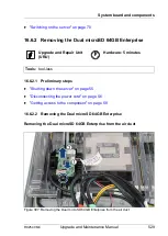
Figure 405: Removing the system board
Ê
Remove the 10 screws (see blue circles, orange circles show the centering
bolts) from the system board (see circles).
Ê
Use both hands to lift the system board carefully out of the chassis in a slight
angle. Thereby you pull the connectors out of the I/O panel (see arrow).
V
CAUTION!
Always take the system board with both hands!
Never lift the system board one-sided or at a heat sink, because the
solder connections between the socket and the system board come
under tension and increase the risk of damage and malfunction!
Don’t damage the EMI springs which are essential to comply with
applicable EMC regulations and satisfy cooling requirements and fire
protection measures.
Ê
Place the removed and the new system board on an antistatic surface.
Ê
Remove the TPM, see section
"Removing the TPM" on page 508
.
Summary of Contents for PRIMERGY RX2540 M4
Page 40: ...40 Upgrade and Maintenance Manual RX2540 M4 Before you start ...
Page 90: ...90 Upgrade and Maintenance Manual RX2540 M4 Basic hardware procedures ...
Page 136: ...136 Upgrade and Maintenance Manual RX2540 M4 Power supply unit PSU ...
Page 228: ...228 Upgrade and Maintenance Manual RX2540 M4 Hard disk drives HDD and solid state drives SSD ...
Page 344: ...344 Upgrade and Maintenance Manual RX2540 M4 Main memory ...
Page 362: ...362 Upgrade and Maintenance Manual RX2540 M4 Processor CPU ...
Page 390: ...390 Upgrade and Maintenance Manual RX2540 M4 Liquid cooling LC ...
Page 498: ...498 Upgrade and Maintenance Manual RX2540 M4 Additional interfaces ...
Page 572: ...572 Upgrade and Maintenance Manual RX2540 M4 Appendix A ...
Page 574: ...574 Upgrade and Maintenance Manual RX2540 M4 Appendix B ...
Page 582: ...8 RX2540 M4 Basic Serial RS 232 Cable plan System Board D3384 RS 232 onboard RS 232 rear C6 ...
Page 634: ...List of all used screws for PRIMERGY Servers Assembled in Germany and Japan January 2017 ...