C141-E034-02EN
5 - 8
5.2.2
Command block registers
(1)
Data register (X'1F0')
The Data register is a 16-bit register for data block transfer between the device and the host
system. Data transfer mode is PIO or LBA mode.
(2)
Error register (X'1F1')
The Error register indicates the status of the command executed by the device. The contents of
this register are valid when the ERR bit of the Status register is 1.
This register contains a diagnostic code after power is turned on, a reset , or the EXECUTIVE
DEVICE DIAGNOSTIC command is executed.
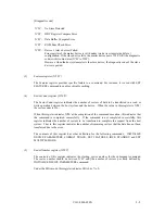
[Status at the completion of command execution other than diagnostic command]
Bit 7
Bit 6
Bit 5
Bit 4
Bit 3
Bit 2
Bit 1
Bit 0
ICRC
UNC
X
IDNF
X
ABRT
TK0NF
AMNF
X: Unused
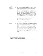
- Bit 7:
Interface CRC error (ICRC). This bit indicates that an interface CRC error has
occurred during an Ultra DMA data transfer. The content of this bit is not applicable
for Multiword DMA transfers.
- Bit 6:
Uncorrectable Data Error (UNC). This bit indicates that an uncorrectable data error
has been encountered.
- Bit 5:
Unused
- Bit 4:
ID Not Found (IDNF). This bit indicates an error except for bad sector,
uncorrectable error and SB not found, and Aborted Command.
- Bit 3:
Unused
- Bit 2:
Aborted Command (ABRT). This bit indicates that the requested command was
aborted due to a device status error (e.g. Not Ready, Write Fault) or the command
code was invalid.
- Bit 1:
Track 0 Not Found (TK0NF). This bit indicates that track 0 was not found during
RECALIBRATE command execution.
- Bit 0:
Address Mark Not Found. This bit indicates that an SB not found error has been
encountered.
Summary of Contents for MPA3017AT
Page 1: ...C141 E034 02EN MPA3017AT MPA3026AT MPA3035AT MPA3043AT MPA3052AT DISK DRIVES PRODUCT MANUAL ...
Page 29: ...C141 E034 02EN 3 2 Figure 3 1 Dimensions ...
Page 44: ...C141 E034 02EN 4 5 Figure 4 2 MPA30xxAT Block diagram ...
Page 50: ...C141 E034 02EN 4 11 Figure 4 4 Read write circuit block diagram ...
Page 52: ...C141 E034 02EN 4 13 Figure 4 6 PR4 signal transfer ...


