C141-E034-02EN
5 - 69
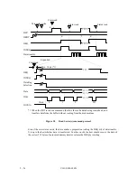
2)
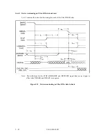
The device shall pause an Ultra DMA burst by negating DDMARDY-.
3)
The host shall stop generating HSTROBE edges within t
RFS
of the device negating
DDMARDY-.
4)
If the device negates DDMARDY- within t
SR
after the host has generated an HSTROBE
edge, then the device shall be prepared to receive zero or one additional data words. If
the device negates DDMARDY- greater than t
SR
after the host has generated an
HSTROBE edge, then the device shall be prepared to receive zero, one or two additional
data words. The additional data words are a result of cable round trip delay and t
RFS
timing for the host.
5)
The device shall resume an Ultra DMA burst by asserting DDMARDY-.
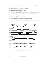
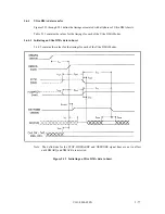
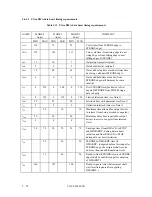
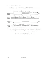
5.5.4.4 Terminating an Ultra DMA data out burst
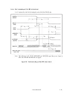
a) Host terminating an Ultra DMA data out burst
The following stops shall occur in the order they are listed unless otherwise specifically
allowed (see 5.6.4.10 and 5.6.4.2 for specific timing requirements):
1)
The host shall initiate termination of an Ultra DMA burst by not generating HSTROBE
edges.
2)
The host shall assert STOP no sooner than t
SS
after it last generated an HSTROBE edge.
The host shall not negate STOP again until after the Ultra DMA burst is terminated.
3)
The device shall negate DMARQ within t
LI
after the host asserts STOP. The device shall
not assert DMARQ again until after the Ultra DMA burst is terminated.
4)
The device shall negate DDMARDY- with t
LI
after the host has negated STOP. The
device shall not assert DDMARDY- again until after the Ultra DMA burst termination is
complete.
5)
If HSTROBE is negated, the host shall assert HSTROBE with t
LI
after the device has
negated DMARQ. No data shall be transferred during this assertion. The device shall
ignore this transition on HSTROBE. HSTROBE shall remain asserted until the Ultra
DMA burst is terminated.
6)
The host shall place the result of its CRC calculation on DD (15:0) (see 5.5.5)
7)
The host shall negate DMACK- no sooner than t
MLI
after the host has asserted HSTROBE
and STOP and the device has negated DMARQ and DDMARDY-, and no sooner than
t
DVS
after placing the result of its CRC calculation on DD (15:0).
8)
The device shall latch the host's CRC data from DD (15:0) on the negating edge of
DMACK-.
9)
The device shall compare the CRC data received from the host with the results of its own
CRC calculation. If a miscompare error occurs during one or more Ultra DMA bursts for
any one command, at the end of the command, the device shall report the first error that
occurred (see 5.5.5).
Summary of Contents for MPA3017AT
Page 1: ...C141 E034 02EN MPA3017AT MPA3026AT MPA3035AT MPA3043AT MPA3052AT DISK DRIVES PRODUCT MANUAL ...
Page 29: ...C141 E034 02EN 3 2 Figure 3 1 Dimensions ...
Page 44: ...C141 E034 02EN 4 5 Figure 4 2 MPA30xxAT Block diagram ...
Page 50: ...C141 E034 02EN 4 11 Figure 4 4 Read write circuit block diagram ...
Page 52: ...C141 E034 02EN 4 13 Figure 4 6 PR4 signal transfer ...

