C141-E034-02EN
5 - 38
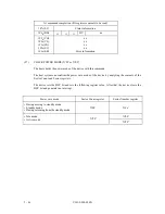
At command issuance (I/O registers setting contents)
1F7
H
(CM)
1
0
0
1
0
0
0
0
1F6
H
(DH)
×
×
×
DV
xx
1F5
H
(CH)
1F4
H
(CL)
1F3
H
(SN)
1F2
H
(SC)
1F1
H
(FR)
xx
xx
xx
xx
xx
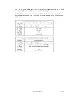
At command completion (I/O registers contents to be read)
1F7
H
(ST)
Status information
1F6
H
(DH)
×
×
×
DV
xx
1F5
H
(CH)
1F4
H
(CL)
1F3
H
(SN)
1F2
H
(SC)
1F1
H
(ER)
xx
xx
01
H
(*1)
01
H
Diagnostic code
*1 This register indicates X‘00’ in the LBA mode.
(17)
FORMAT TRACK (X'50')
Upon receipt of this command, the device sets the DRQ bit and waits the completion of 512-byte
format parameter transfer from the host system. After completion of transfer, the device clears the
DRQ bits, sets the BSY bit. However the device does not perform format operation, but the drive
clears the BYS bit and generates an interrupt soon. When the command execution completes, the
device clears the BSY bit and generates an interrupt.
The drive supports this command for keep the compatibility with previous drive only.
(18)
READ LONG (X'22' or X'23')
This command operates similarly to the READ SECTOR(S) command except that the device
transfers the data in the requested sector and the ECC bytes to the host system. The ECC error
correction is not performed for this command. This command is used for checking ECC function
by combining with the WRITE LONG command.
Number of ECC bytes to be transferred is fixed to 4 bytes and cannot be changed by the SET
FEATURES command.
The READ LONG command supports only single sector operation.
Summary of Contents for MPA3017AT
Page 1: ...C141 E034 02EN MPA3017AT MPA3026AT MPA3035AT MPA3043AT MPA3052AT DISK DRIVES PRODUCT MANUAL ...
Page 29: ...C141 E034 02EN 3 2 Figure 3 1 Dimensions ...
Page 44: ...C141 E034 02EN 4 5 Figure 4 2 MPA30xxAT Block diagram ...
Page 50: ...C141 E034 02EN 4 11 Figure 4 4 Read write circuit block diagram ...
Page 52: ...C141 E034 02EN 4 13 Figure 4 6 PR4 signal transfer ...


