


C141-E034-02EN
5 - 40
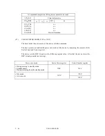
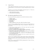
At command issuance (I/O registers setting contents)
1F7
H
(CM)
0
0
1
1
0
0
1
R
1F6
H
(DH)
×
L
×
DV
Head No. /LBA [MSB]
1F5
H
(CH)
1F4
H
(CL)
1F3
H
(SN)
1F2
H
(SC)
1F1
H
(FR)
Cylinder No. [MSB] / LBA
Cylinder No. [LSB] / LBA
Sector No.
/ LBA [LSB]
Number of sectors to be transferred
xx
R = 0
→
with Retry
R = 1
→
without Retry
At command completion (I/O registers contents to be read)
1F7
H
(ST)
Status information
1F6
H
(DH)
×
L
×
DV
Head No. /LBA [MSB]
1F5
H
(CH)
1F4
H
(CL)
1F3
H
(SN)
1F2
H
(SC)
1F1
H
(ER)
Cylinder No. [MSB] / LBA
Cylinder No. [LSB] / LBA
Sector No.
/ LBA [LSB]
00 (*1)
Error information
*1 If the command is terminated due to an error, this register indicates 01.
(20)
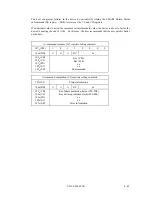
READ BUFFER (X'E4')
The host system can read the current contents of the sector buffer of the device by issuing this
command. Upon receipt of this command, the device sets the BSY bit of Status register and sets
up the sector buffer for a read operation. Then the device sets the DRQ bit of Status register,
clears the BSY bit, and generates an interrupt. After that, the host system can read up to 512 bytes
of data from the buffer.
At command issuance (I/O registers setting contents)
1F7
H
(CM)
1
1
1
1
0
1
0
0
1F6
H
(DH)
×
×
×
DV
xx
1F5
H
(CH)
1F4
H
(CL)
1F3
H
(SN)
1F2
H
(SC)
1F1
H
(FR)
xx
xx
xx
xx
xx
Summary of Contents for MPA3017AT
Page 1: ...C141 E034 02EN MPA3017AT MPA3026AT MPA3035AT MPA3043AT MPA3052AT DISK DRIVES PRODUCT MANUAL ...
Page 29: ...C141 E034 02EN 3 2 Figure 3 1 Dimensions ...
Page 44: ...C141 E034 02EN 4 5 Figure 4 2 MPA30xxAT Block diagram ...
Page 50: ...C141 E034 02EN 4 11 Figure 4 4 Read write circuit block diagram ...
Page 52: ...C141 E034 02EN 4 13 Figure 4 6 PR4 signal transfer ...


