C156-E097-01EN
7 - 1
CHAPTER 7
SCSI BUS
7.1
System Configuration
7.2
Interface Signal Definition
7.3
Electrical Requirements
7.4
Timing Rule
7.5
Bus Phases
7.6
Bus Conditions
7.7
Bus Sequence
This chapter describes the structure of the SCSI bus, electrical conditions, interface protocol and their
operations.
IMPORTANT
The ODD operates on the SCSI bus as a TARG. In this chapter, the
ODD is represented as "TARG" except where some special distinction
must be made.
7.1
System Configuration
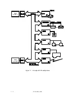
Up to eight SCSI divices can be connected to the SCSI bus. Figure 7.1 shows sample system
configurations. Communication on the SCSI bus is allowed between only two SCSI divices, an
initiator (INIT) and a target (TARG), at any given time.
In the configured system, any combination is allowed for an SCSI device to work as an INIT and
as a TARG. Also, there may be an SCSI device that works as both an INIT and a TARG.
A unique address (SCSI ID) is assigned to each SCSI device. The SCSI ID corresponds to one
bit of the SCSI data bus. The INIT designates an I/O device connected to the TARG by its
logical unit number (LUN).
The SCSI ID of the ODD can be selectable among #0 to #7, but the LUN is fixed to #0.
Summary of Contents for MCE3064SS
Page 1: ...C156 E097 01EN MCE3064SS MCF3064SS OPTICAL DISK DRIVES PRODUCT MANUAL ...
Page 3: ...This page is intentionally left blank ...
Page 31: ...This page is intentionally left blank ...
Page 52: ...C156 E097 01EN 2 21 Figure 2 3 Example of alternate processing ...
Page 53: ...This page is intentionally left blank ...
Page 72: ...C156 E097 01EN 3 19 Figure 3 17 SCSI cable connector ...
Page 81: ...This page is intentionally left blank ...
Page 97: ...4 16 C156 E097 01EN Figure 4 5 SCSI connection check 2 ...
Page 99: ...This page is intentionally left blank ...
Page 113: ...This page is intentinally left blank ...
Page 119: ...7 2 C156 E097 01EN Host system A Host system B Figure 7 1 Example of SCSI configuration ...
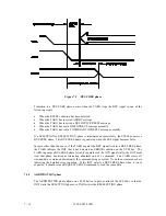
Page 133: ...7 16 C156 E097 01EN Figure 7 6 ARBITRATION phase ...
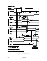
Page 135: ...7 18 C156 E097 01EN µ Figure 7 7 SELECTION phase 30 30 30 30 ...
Page 141: ...7 24 C156 E097 01EN Figure 7 10 Transfer in asynchronous mode 18 18 ...
Page 145: ...7 28 C156 E097 01EN Figure 7 11 Transfer in synchronous mode 11 11 11 11 43 18 43 18 ...
Page 146: ...C156 E097 01EN 7 29 Figure 7 12 Transfer in FAST SCSI mode ...
Page 148: ...C156 E097 01EN 7 31 Figure 7 13 Data transfer rate in asynchronous mode ...
Page 158: ...C156 E097 01EN 7 41 Figure 7 17 RESET condition ...
Page 160: ...C156 E097 01EN 7 43 Figure 7 18 Bus phase sequence 1 of 2 ...
Page 161: ...7 44 C156 E097 01EN Figure 7 18 Bus phase sequence 2 of 2 ...
Page 167: ...This page is intentionally left blank ...
Page 171: ...This page is intentionally left blank ...
Page 181: ......

