C156-E097-01EN
5 - 1
CHAPTER 5
OPERATION AND CLEANING
5.1
Operating Optical Disk Drive
5.2
Cleaning Drive
5.3
Optical Disk Cartiridge Operation
5.4
Cleaning Optical Disk Cartiridge
This chapter describes how to operate and clean the drive and the optical disk cartridges.
5.1
Operating Optical Disk Drive
The drive has an automatic load function. All the operator must do is to insert the optical disk
cartridge and operate the eject button.
This section explains loading and ejection methods, assuming that the drive is mounted
horizontally. (When mounted vertically, the drive is operated in the same manner as when
mounted horizontally.)
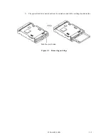
Figure 5.1 shows the front view of the optical disk drive. For operation, users should be familiar
with the parts in the figure and their function. Loading and ejection methods are described
below.
5.1.1
Optical disk drive
Figure 5.1
Optical disk drive front view (with panel)
The following explains the parts and functions of the optical disk drive (the following numbers
correspond to the numbers in Figures 5.1):
2) Eject button/
BUSY LED
1) Disk insertion slot
3) Manual eject hole
Summary of Contents for MCE3064SS
Page 1: ...C156 E097 01EN MCE3064SS MCF3064SS OPTICAL DISK DRIVES PRODUCT MANUAL ...
Page 3: ...This page is intentionally left blank ...
Page 31: ...This page is intentionally left blank ...
Page 52: ...C156 E097 01EN 2 21 Figure 2 3 Example of alternate processing ...
Page 53: ...This page is intentionally left blank ...
Page 72: ...C156 E097 01EN 3 19 Figure 3 17 SCSI cable connector ...
Page 81: ...This page is intentionally left blank ...
Page 97: ...4 16 C156 E097 01EN Figure 4 5 SCSI connection check 2 ...
Page 99: ...This page is intentionally left blank ...
Page 113: ...This page is intentinally left blank ...
Page 119: ...7 2 C156 E097 01EN Host system A Host system B Figure 7 1 Example of SCSI configuration ...
Page 133: ...7 16 C156 E097 01EN Figure 7 6 ARBITRATION phase ...
Page 135: ...7 18 C156 E097 01EN µ Figure 7 7 SELECTION phase 30 30 30 30 ...
Page 141: ...7 24 C156 E097 01EN Figure 7 10 Transfer in asynchronous mode 18 18 ...
Page 145: ...7 28 C156 E097 01EN Figure 7 11 Transfer in synchronous mode 11 11 11 11 43 18 43 18 ...
Page 146: ...C156 E097 01EN 7 29 Figure 7 12 Transfer in FAST SCSI mode ...
Page 148: ...C156 E097 01EN 7 31 Figure 7 13 Data transfer rate in asynchronous mode ...
Page 158: ...C156 E097 01EN 7 41 Figure 7 17 RESET condition ...
Page 160: ...C156 E097 01EN 7 43 Figure 7 18 Bus phase sequence 1 of 2 ...
Page 161: ...7 44 C156 E097 01EN Figure 7 18 Bus phase sequence 2 of 2 ...
Page 167: ...This page is intentionally left blank ...
Page 171: ...This page is intentionally left blank ...
Page 181: ......

