background image

S e c t i o n   F i v e

162

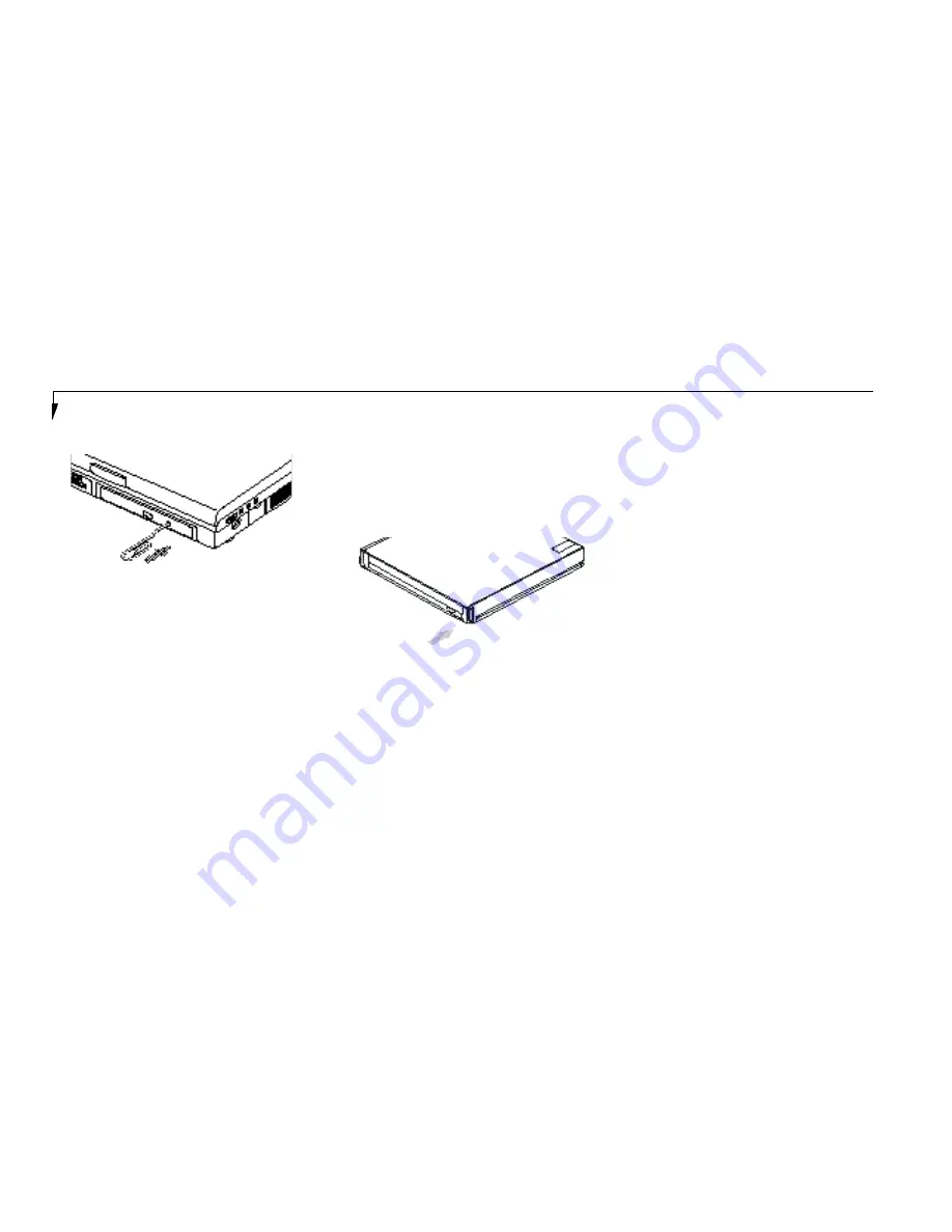
EMERGENCY CD-ROM TRAY RELEASE

If for some reason the eject button fails, you
can open the CD-ROM tray with a paper clip
or similar tool inserted into the eject hole in the
far right side of the front of the tray. Straighten
one side of a paper clip and push it gently into
the hole. The tray will pop out a short distance.

EMERGENCY ZIP DISK RELEASE

If for some reason the eject button fails, you
can eject a disk from the Zip drive with a paper
clip or similar tool inserted into the eject hole
in the center of the eject button. Straighten one
side of a paper clip and push it gently into the
hole. The disk will pop out a short distance.

If the disk does eject easily, remove the paper
clip and repeat the process. Under no circum-
stances should you use excessive force in trying
to remove a Zip disk from the drive as this may
damage the drive.

your screen to keep you informed of the actions
of your modem. The operating system and
application software may suppress display of
the result codes.

Examples of result codes are:

OK
NO CARRIER
NO DIALTONE
CONNECT 56000

(Connection complete at 56,000 bps.)

ERROR
FAX
RING (This means an incoming call.)
BUSY
NO ANSWER

When using the internal modem with applica-
tions which are not factory installed see the
application documentation.

Figure 5-1 Emergency CD-ROM Tray Release

MODEM SETUP AND COMMANDS

The operating system and application software
that is factory installed detects the modem
characteristics and provides the necessary com-
mand strings to operate the modem. The inter-
nal modem operation is controlled by generic
AT commands from the operating system and
application software. The standard long form
result codes may, in some cases, be displayed on

Figure 5-2 Emergency Zip disk Release  

Summary of Contents for LifeBook 200 Series

Page 1: ...ink is a registered trademark of Traveling Software Inc AudioRack is a registered trademark of ESS Technology Inc MegaPhone is a registered trademark of AVEO Inc All other trademarks mentioned herein are the property of their respective owners We cannot guarantee the accuracy of the contents of this document We disclaim liability for errors omissions or future changes Copyright 1998 Fujitsu PC Cor...

Page 2: ...ENs contact your local telephone company If this equipment causes harm to the telephone net work your telephone company may discontinue your service temporarily If possible they will notify you in advance If advance notice is not practical they will notify you as soon as possible You will also be advised of your right to file a complaint with the FCC This fax modem also complies with fax branding ...

Page 3: ...ique de la class B respecte toutes les exigence du Réglement sur le matérial brouilleur du Canada Notice to Users of the Canadian Telephone Network The Canadian Industry Canada label identifies certi fied equipment This certification means that the equipment meets certain telecommunications net work protective operational and safety requirements The Department does not guarantee the equipment will...

Page 4: ...es par un service de maintenance agréé au Canada Toute réparation ou modification qui n est pas expressément approuvée par Fujitsu PC Corp C A U T I O N For safety users should ensure that the electrical ground of the power utility the telephone lines and the metallic water pipes are connected together Users should NOT attempt to make such connections themselves but should contact the appropriate ...

Page 5: ...n WARNING CMOS and NiCAD batteries may explode if mistreated Do not recharge disassemble or dispose of in fire A V E R T I S S E M E N T Pour assurer la sécurité les utilisateurs doivent vérifier que la prise de terre du service d électricité les lignes télphoniques et les conduites d eau métalliques sont connectées ensemble Les utilisateurs NE doivent PAS tenter d établir ces connexions eux mêmes...

Page 6: ...T a b l e o f C o n t e n t s ...

Page 7: ...ng The System 25 Batteries 26 Fujitsu Welcome Center 26 Integrated ErgoTracTM Pointing Device 30 Using The Keyboard 32 Volume Control 34 Floppy Disk Drive 34 CD ROM Drive 36 Iomega Zip Drive 38 Hard Drive 39 Power Management 40 Internal Modem 48 Infrared Port 48 Pre Installed Software 49 SECTION THREE CONFIGURING YOUR LIFEBOOK 200 SERIES FROM FUJITSU Boot Sequence 52 Identifying the Drives 52 BIOS...

Page 8: ...e Module 126 LANdock 130 Port Replicator 134 SECTION FIVE TROUBLESHOOTING Identifying the Problem 138 Specific Problems 139 Power On Self Test Messages 159 Emergency CD ROM Drive Tray Release 162 Emergency Zip Disk Release 162 Modem Setup and Commands 162 Restoring Your Pre Installed Software From CD ROM 163 SECTION SIX CARE AND MAINTENANCE Care and Maintenance 166 Caring for your Notebook 166 Inc...

Page 9: ...Li feB oo k 2 0 0 Se ries fr om Fu jit su P r e f a c e ...

Page 10: ...olor LCD display It has a powerful interface that enables it to support a variety of optional features Figure P 1 CONVENTIONS USED IN THE GUIDE Screen examples in this manual are intended as examples only and screen and file names may differ in actual use Messages displayed by the LifeBook 200 Series appear in Courier type Example Shutdown the computer Keyboard keys are shown in boldface Helvetica...

Page 11: ...L i f e B o o k 2 0 0 S e r i e s f r o m F u j i t s u L if e B o ok 2 0 0 S e r ie s f r om F uj i t su vii Figure P 1 LifeBook 200 Series with Both Fujitsu and Third Party Options ...

Page 12: ...nent Identification 5 Top and Front Components 6 Left side Panel Components 7 Right side Panel Components 8 Rear Panel Components 9 Bottom Components 10 Power Sources 11 Data Security 12 Starting Your Notebook for the First Time 13 User Registration 15 Learning About Your Operating System and Application Software 15 ...

Page 13: ...ccessories box Figure 1 2 Modular Lithium ion battery Already installed in Multi function Bay 1 of your notebook Modular 20 speed maximum CD ROM drive Already installed in Multi function Bay 2 of your notebook Modular 100Mb Iomega Zip removable media drive located in the Accessories box Figure 1 3 Bay Adapter for Multi function Bay 2 located in the Accessories box Figure 1 4 Modular 3 5 floppy dis...

Page 14: ... SDRAM standard expandable to 96MB 12 1 HPA dual scan DSTN color display with 800 x 600 resolution 2MB EDO video RAM Built in 2 1GB or 3 2GB hard drive Dual Multi function bays which support the following 3 5 floppy disk drive included with all models 20 speed maximum CD ROM drive included with all models for Bay 2 only 100MB Iomega Zip drive included with all models Optional second 3 2GB hard dri...

Page 15: ...dard pre installed software Microsoft Windows 95 operating system LapLink for file transfers via modem cable or infrared port Microsoft Works for business applications including word processing spreadsheets and databases Quicken Basic 98 for money management PC Doctor for system diagnostics Phoenix PowerPanel for system power management SoftPEG from CompCore an MPEG 1 video player McAfee VirusScan...

Page 16: ...ith Display Open Display Panel Status Indicator Panel Keyboard ErgoTrac Pointing Device Multi function Bay 1 Multi function Bay 2 Closed Cover Switch Suspend Resume button Built in Microphone Brightness Control Display Panel Latch COMPONENT IDENTIFICATION For detailed specifications on each model refer to Appendix A on pages 150 163 Contrast Control ...

Page 17: ...isk drive activity hard drive or Zip drive activity CD ROM drive activity PC Card activity CapsLock NumLk and Scr Lk Figure 1 6 Suspend Resume Button The Suspend Resume button allows you to sus pend notebook activity without turning off the notebook power and to return it to an active state This feature saves power and is particu larly useful when the notebook is running only on battery power See ...

Page 18: ... ion battery mounted in the Bay Adapter for Multi function Bay 2 a second battery can be purchased separately for a dual battery configuration Optional second 3 2GB hard drive which must be purchased separately 3 5 floppy disk drive mounted in the Bay Adapter for Multi function Bay 2 C A U T I O N Do not use your notebook with either of the Multi function bays empty It may damage your notebook LEF...

Page 19: ...ows you to connect Universal Serial Bus devices such as external game pads pointing devices keyboards and speakers Figure 1 8 DC Power Jack The DC power jack allows you to plug in the AC adapter or the optional auto airline adapter Figure 1 8 Power Switch This switch is the main power switch for your notebook Figure 1 8 Right Speaker The built in dual speakers output stereo sound from the notebook...

Page 20: ... sliding panel in the connector cover slightly opened for added convenience Figure 1 9 Figure 1 9 LifeBook 200 Series Rear Panel RJ 11 Jack Docking Port Serial Port Parallel Port External Monitor Port Infrared Port Connector Cover Slide Panel C A U T I O N The cover which closes over the ports on the rear of the notebook can be damaged if it is left open when the notebook is moved around Docking P...

Page 21: ...otebook See Figure 1 6 on page 5 Parallel Port The parallel port allows you to connect parallel devices such as a parallel printer to your notebook This is also sometimes referred to as an LPT port Figure 1 9 External Monitor Port This port allows you to connect an external VGA or SVGA CRT monitor Figure 1 9 Infrared Port The fast IrDA 4Mbps compatible port allows you to communicate with another I...

Page 22: ...nal auto airline adapter provides power for operating your notebook and charging the batteries Figure 1 11 To Connect the AC Adapter 1 Plug the DC Output cable of the AC adapter into the DC Power jack on the right side panel of your notebook 2 Plug the AC adapter into an AC electrical outlet To Connect the Optional Auto airline Adapter 1 Plug the DC Output cable into the DC Power jack on the right...

Page 23: ...uthorized access Hardware Data Security Features When you are using your notebook built in hardware control password to gain access to the notebook the actual password will not appear on the screen This is a safety precaution The hardware control security parameters are set from the BIOS setup utility See Security Menu on pages 77 80 for more information on setting and clearing passwords and enabl...

Page 24: ...er without using the on screen Cancel button you will get an error message when you start your notebook again Conditions of Use Process The first time you start your notebook you must confirm your acceptance of the copyright limitations for your pre installed software After you complete the Condition of Use process these screens will not appear again There are 6 screens to read carefully and respo...

Page 25: ...system identifies what hard ware is installed and runs a virus check Time Zone When your notebook has completely identified all of the installed hardware it will display a dialog box for entering which time zone you wish to set the clock to Windows Messaging Once you have selected a time zone you will see a screen announcing that Windows messaging is being set up Printer Setup When the messaging s...

Page 26: ...application even if you are familiar with the same application on a different machine an earlier version of the application or a similar product Manuals In the accessories box you will find manuals for Windows 95 and other pre installed software Software manuals of pre installed software that are not in the accessories box are available online See the help screens of your pre installed software We...

Page 27: ...r Panel 19 Power On 23 Power Off 24 Restarting the System 25 Fujitsu Welcome Center 26 Batteries 26 Integrated ErgoTrac Pointing Device 30 Using the Keyboard 32 Volume Control 34 Floppy Disk Drive 34 CD ROM Drive 36 Iomega Zip Drive 38 Hard Drive 39 Power Management 40 Internal Modem 48 Infrared Port 48 Pre installed Software 49 ...

Page 28: ...el When you turn on your notebook you may want to adjust the brightness level of the screen for best visibility To do this adjust the bright ness control slider on the right side of the dis play panel Figure 2 2 You may need to adjust the brightness periodically for different Figure 2 1 Opening the Display Panel P O I N T The higher the brightness level the more power the notebook will consume and...

Page 29: ... 3 The appropriate indicators become visible as you use your notebook Power Indicator The Power indicator tells you when the system is operational It is on steady when there is power to your notebook and blinks when the system is in Suspend mode It goes off when the system has entered Save to Disk mode has entered the Windows 95 pseudo off state or the power is turned off from the power switch C A...

Page 30: ...e AC Adapter indicator and the Battery indicators will all be Off Battery Indicators The two sets of battery indicators show whether or not the primary Lithium ion battery and or the optional second Lithium ion battery are installed and indicate the condition of each Figure 2 3 Battery 1 is the Lithium ion bat tery which is installed in Multi function Bay 1 and Battery 2 is the Lithium ion battery...

Page 31: ...harging and the power switch is Off then the AC Adapter indicator and the Battery indicators will all be off C A U T I O N Turning off the power with the power switch or using the Suspend Resume button when any of the Access indicators are On may cause loss of data and or system errors C A U T I O N A shorted battery is damaged and must be replaced See Figure 2 4 C A U T I O N Batteries subjected ...

Page 32: ...k on the System icon The system properties dialogue box will be displayed 6 Click on the Device Manager tab The device list will be displayed 7 Click on the to the left of the CD ROM icon The CD ROM drive manufacturer s name and model will be displayed 8 Click on the CD ROM drive manufacturer s name and model 9 Click on Properties The CD ROM drive manufacturer s name and model properties dialogue ...

Page 33: ...n the numeric keypad You can activate the NumLk mode by pressing the NumLk Scr Lk key while holding down the Shift key Deactivate the mode the same way that you activated it CapsLock Indicator The CapsLock indicator tells you when the key board is set for all capital letters Activate the all capital letters setting by pressing the CapsLock key on the keyboard Deactivate the mode the same way that ...

Page 34: ...bject it to shocks or vibration as you risk damaging your notebook When the power switch is turned on your notebook carries out a Power On Self Test POST to check the internal parts and config uration If a fault is found a beep will sound and or an error message will be displayed See Troubleshooting on pages 138 140 Depend ing on the nature of the problem you may be able to continue by starting th...

Page 35: ...e button You may also select Shut down the computer and once the power is off turn the power switch to Off for 10 seconds or more and then turn the power switch to On These alternative methods are not recommended C A U T I O N Never turn your notebook off while an application is running Be sure to close all files exit all applications and shut down your operating system prior to turning off the po...

Page 36: ...llowing conditions When used at temperatures that exceed a low of 5 C or a high of 35 C High temperatures not only reduce charging efficiency but can also cause battery deterioration The Charging icon on the Status Indicator panel will flash when you try to charge a battery that is outside its operating temperature range The battery charging capacity is reduced as the battery ages If your battery ...

Page 37: ...bout 3 minutes and can vary with the condition of your notebook C A U T I O N Do not leave a faulty battery in your notebook It might damage your AC adapter optional auto airline adapter another battery or your notebook itself It may also prevent operation of your notebook by draining all available current into the bad battery C A U T I O N Under federal state or local law it may be illegal to dis...

Page 38: ...ct on the Lithium ion batteries which means that you do not need to discharge them completely before recharging A single fully discharged Lithium ion battery will charge in approximately three 3 hours when your notebook is Off or in Suspend mode The charging time from fully discharged for two Lithium ion batteries together is approximately 5 hours when your notebook is Off or in Suspend mode Of co...

Page 39: ...ur data can be maintained for sometime If a power source is not provided promptly the Power indicator will stop flashing and go out and you will have lost the data that was not stored Once you provide power you can continue to use your notebook while an adapter is charging the battery but the battery trickle charges under these conditions If you want to charge the battery more quickly put your not...

Page 40: ...ll that is required to operate the ErgoTrac The more pressure you use the faster the cursor will move The second part of the ErgoTrac pointing device the buttons function as mouse but tons and the functions they perform depend on the application you are running Figure 2 6 shows the position of the ErgoTrac pointing device and buttons Figure 2 6 ErgoTrac pointing device Right Button Left Button Cur...

Page 41: ... item with the pointing cursor and while keeping the left pointing device button depressed moving the cursor to the desired new location then releas ing the button Figure 2 8 Figure 2 7 Clicking Left Click Left Double Click C A U T I O N If the interval between clicks is too long double clicking will not be executed P O I N T The interval between presses for double clicking and other parameters of...

Page 42: ...nal mouse You may want to try practicing with different adjustments until you find a combination that is comfortable for you USING THE KEYBOARD Your notebook has an integral 86 key keyboard Figure 2 9 The keys perform all the standard functions of a 101 key keyboard and also include Windows 95 keys and other special function keys This section describes only those items specific to your notebook Th...

Page 43: ...e holding down the Fn key allows you to change your selection of where to send your display video Each time you press the combination of keys you will step to the next choice The choices in order are built in dis play panel only external monitor only or both built in display panel and external monitor Windows 95 Keys Your notebook has three Windows 95 keys two Start keys and an Application key The...

Page 44: ...her application software C A U T I O N The ESS AudioRack volume setting sets the maximum volume level of the hardware volume control knob treat any floppy disk drive in exactly the same way regardless of where it is installed For floppy disk drive installation and removal instructions see Multi function Bays on pages 97 100 and External Installation of a Floppy Disk Drive on page 107 When your sys...

Page 45: ... Disk P O I N T When there is no floppy disk in the drive the Eject button is flush with the front of your notebook C A U T I O N If you eject the disk while the Floppy Disk Drive Access indicator is On there is a risk of damaging the data on the disk or the disk drive Figure 2 11 Floppy Disk Write Protect Preparing a Floppy Disk for Use Before you can use a new floppy disk you need to prepare it ...

Page 46: ... operate your CD ROM drive unless your notebook is sitting on a flat surface and the adjustment feet are folded against the bottom of the notebook Using a CD when the drive is not level may damage the drive or prevent proper operation Care of Floppy Disk Drives and Disks Avoid storing the floppy disk drive and disks in extremely hot and cold locations or in locations subject to severe temperature ...

Page 47: ...ertion function you will have to start the CD from your desktop as your notebook will not automatically recognize that the CD has been loaded When removing the CD ROM from its case press down on the holder s center while lift ing out the CD ROM by its edges Always handle a CD ROM by the edges and avoid touching the surface Avoid storing any CD ROM in extreme temperatures Do not bend CD ROMs or set...

Page 48: ... the Zip disk then reinsert it To remove a Zip disk press the gray button on the front of the drive or click on the Zip 100 icon in the My Computer window with the right mouse button and select eject When you remove a Zip disk from the drive store it in the protective case The Zip drive will automatically eject the disk when you shut down your LifeBook 200 Series notebook Store all your Zip disks ...

Page 49: ... disk eject procedure as described above Zip Disk Tips Never force a Zip disk into or out of the drive It is a good idea to return the Zip disk to its case when it is not in use Avoid exposing Zip disks to direct sunlight high temperature moisture and magnetic fields Read Write Protecting Zip Disks Your Zip Tools software includes a special read write protect feature that lets you Write protect a ...

Page 50: ...gement parameters are covered under the Power Savings menu See pages 81 87 Some particular power parameters are only available for setup from one of these places others can be changed in any one of them Using the Suspend Resume Button When your notebook is active the Suspend Resume button Figure 1 7 on page 7 can be used to manually put your notebook into Suspend mode or into the Save to Disk mode...

Page 51: ...enter the Suspend or Save to Disk mode changes to open files are not lost The files are left open and memory is kept active during Suspend mode or the memory is transferred to the internal hard drive during Save to Disk mode C A U T I O N Be sure you know which settings are active for the Suspend Resume button before you use it misuse can result in data loss See the Power Savings Menu of the BIOS ...

Page 52: ...om the PowerPanel application some can be edited and saved from the BIOS setup utility and only viewed from PowerPanel and some are factory set and can only be viewed from either PowerPanel or the BIOS setup utility The profile choices are This group is factory set Maximum Battery Life Maximum Performance Power Management Off This one is set only from the BIOS setup utility Custom Settings This gr...

Page 53: ...ters read directly from the BIOS and chosen as the settings that will produce the longest possible battery life MAXIMUM PERFORMANCE PROFILE The Maximum Performance profile is a factory installed combination of timeouts and other power savings parameters read directly from the BIOS and chosen as the settings that will produce superior performance with reasonable battery life POWER MANAGEMENT OFF Tu...

Page 54: ...nd Resume button turns the power back on and lets you begin where you left off See Figure 2 14 on page 42 and Suspend Mode on pages 47 and 88 SYSTEM SAVE TO DISK ACTIVATION Clicking on the Save to Disk button or select ing System Save to Disk on the PowerPanel menu will put your notebook in Save to Disk mode Your notebook will be left in the Windows 95 pseudo off state If the power switch is not t...

Page 55: ... your notebook s system memory during periods of inactivity by maintaining power to critical parts while turning off the CPU the display the hard drive and all of the other internal components except those necessary to maintain system memory recognize the Suspend Resume button and restart Your notebook can be put in Suspend mode by Pressing the Suspend Resume button until acknowledged Selecting Su...

Page 56: ...n automatically shuts off power to your notebook This is the same pseudo off state as the Windows 95 power off When you resume operation by pressing the Suspend Resume button you return to the point in the operation where you left off before going into Save to Disk mode P O I N T If power is lost during Save to Disk mode the data will be retrieved automatically as soon as power is returned P O I N...

Page 57: ...e from the desktop Selecting Allow Windows to manage power use on this computer allows the operating system to enable Phoenix Technologies PowerPanel and Windows 95 Control panel settings When Windows 95 power management is disabled the BIOS setup utility settings will control your power saving parameters See pages 81 87 for the BIOS setup utility Power Savings menu The Windows 95 Control Panel Po...

Page 58: ... allows for wireless data transfer between your notebook and other IrDA compatible devices Examples of IrDA compatible devices are another computer or a printer When carrying out this kind of C A U T I O N Do not move either device during communication as it may interrupt data transmission communication both devices must be set so their infrared ports are directly facing each other without obstruc...

Page 59: ...ening the desired file will play it Online help screens are available for more information Located in the Multimedia Software folder SoftPEG Video CD Player This control resembles a VCR player front panel and is operated in the same way When you point to a button a small explanation of the use of the button will appear When you left click on the button it will activate Online help screens are avai...

Page 60: ...ncluded See the LapLink online help screens for operating instructions Located in the Communications Software folder MegaPhone MegaPhone by Cypress Research Corporation is telephony software which provides access to the voice and fax features of your notebook s inter nal modem It features dialing speakerphone and caller ID and fax functions See your MegaPhone online help screens for guidance in op...

Page 61: ...etting Standard System Parameters 56 Advanced Menu Setting Device Feature Controls 65 Security Menu Setting the Security Features 87 Power Menu Setting Power Management Feature Controls 93 Boot Menu Selecting the Operating System Source 101 Info Menu Displaying Basic System Information 105 Exit Menu Leaving the Setup Utility 107 Setting Up Your Save To Disk File Allocation 110 ...

Page 62: ...devices such as hard drives floppy disk drives Zip drives CD ROM drives and PC Cards The most commonly assigned drive design ators are listed below If you add other devices the drive designators may be different See your operating system manual for setting drive designations Drive Designators A Floppy disk drive Installable in either of the multi function bays of your notebook or use the external ...

Page 63: ...utility settings if you want to Change the date or time You can also do this without entering the setup utility through your operating system See your operating system manual Change the primary boot device Change the power management parameter settings For a more convenient process see the PowerPanel on pages 40 43 Change a port address or other parameter Change an audio parameter setting Change t...

Page 64: ...ee pages 138 140 3 If an error message is displayed on the screen and you want to enter the setup utility press the F2 key 4 When the setup utility starts with a fault pre sent the system displays the following message Warning Error message Continue 5 Press any key to enter the setup utility The system will then display the Main Menu with current parameters values Entering the Setup Utility After ...

Page 65: ...N T Selecting a field causes a help message about that field to be displayed on the right hand side of the screen P O I N T Pressing the Enter key with the highlight on a selection that is not a submenu or auto selection will cause a list of all options for that item to be displayed Pressing the Enter key or Esc key will select the highlighted choice and remove the list 7 Pressing the F9 key reset...

Page 66: ... 55 Table 3 1 shows the names of the menu fields for the Main menu all of the options for each field the default settings and a description of the field s function and any special information needed to help understand the field s use P O I N T System Time and System Date can also be set from your operating system without using the setup utility Use the calendar and time icon on your Control panel ...

Page 67: ...Y for example 03 20 1996 You may change each segment of the date separately Move between the segments with the Tab key and or Shift Tab keys Legacy Diskette A Disabled 1 44 1 25MB 3 5 Sets the format for floppy disk drive A if it is installed Primary Master Selects Primary Display the type of device on this ATA ATAPI interface if there is Master submenu one Pressing the Enter key selects the Prima...

Page 68: ... 640 KB Displays the size of system memory which is detected automatically and cannot be changed by the setup utility Extended Memory 31 MB Displays the size of extended memory which is detected automatically and cannot be changed by the setup utility Memory Cache Selects the memory Allows you to set your system to use external memory cache cache submenu Language English US Japanese JP English US ...

Page 69: ...ayed at the top of the screen as well as on Main menu Follow the instructions for Navigating Through the Setup Utility to make any changes See page 55 Table 3 2 shows the names of the menu fields for the Primary Master submenu all of the options for each field the default settings and a description of the field s function and any special information needed to help understand the field s use Figure...

Page 70: ... 65 535 identified as hard disk or User is selected When User is selected you can change the value This field is changed by incrementing pressing the Spacebar or by typing in the number Heads A number between 1 and 16 This item appears only when Auto is selected and the type is identified as hard disk or User is selected When User is selected you can change the value This field is changed by incre...

Page 71: ...Disabled Enables or disables logical Block Addressing in place of Cylinder Head Sector addressing This option cannot be changed when Auto is selected Transfer Mode Standard Fast PIO 1 Fast PIO 2 Selects the method for moving data to from the drive Autotype Fast PIO 3 Fast PIO 4 the drive to select the optimum transfer mode This option Fast PIO 3 DMA cannot be changed when Auto is selected Multi wo...

Page 72: ... format CD ROM is used the CD ROM becomes Drive A If a hard disk format CD ROM is used the internal hard drive becomes Drive D and the CD ROM becomes Drive C and all other drive designations shift as necessary The boot sequence ignores the new drive designations however your application software will use the new designations C A U T I O N Be careful of the operating environment when booting from a...

Page 73: ...cache memory for your processor Follow the instructions for Navigating Through the Setup Utility to make any changes See page 55 Table 3 3 shows the names of the menu fields for the Memory Cache submenu all the options for each field the default settings and a description of the field s function and any special informa tion needed to help understand the field s use Figure 3 3 Memory Cache Submenu ...

Page 74: ...ache Submenu Exiting from the Main Menu When you have finished setting the parameters on this menu you can either exit from the setup utility or move to another menu If you wish to exit from the setup utility press the Esc key or use the cursor keys to go to the Exit menu If you wish to move to another menu use the cursor keys See Navigating Through the Setup Utility on page 55 for more informatio...

Page 75: ...EATURE CONTROLS The Advanced Menu allows you to Enable or disable support for Plug Play operating systems Enable or disable BIOS support for ACPI Set the I O addresses for the serial and parallel ports Set the communication mode for the parallel port Set an audio function I O address interrupt level and DMA channel Select between the display panel and an external CRT display Enable or disable comp...

Page 76: ...n which allows the user to modify settings for parallel and serial ports the floppy disk controller and the local bus IDE adapter Keyboard Mouse Features When selected opens the Keyboard Mouse Features submenu which allows setting external and internal keyboard and mouse parameters Multimedia Device When selected opens the Multimedia Device Configuration Configuration submenu which allows setting ...

Page 77: ...ptions and Defaults for the Advanced Menu Menu Field Options Default Description PCI Configuration When selected opens additional menus to configure PCI devices DMI Event Logging When selected opens the DMI event logging configuration menu ACPI Features When selected opens the ACPI features menu which allows enabling and disabling ACPI BIOS ...

Page 78: ...ion normally Please keep a record of original settings before making any changes in the event that a restoration is required See your hardware and software documentation as well as the setup utility to determine settings limitations etc I O Device Configuration Submenu of the Advanced Menu The I O Device Configuration submenu provides the ability to set the I O addresses and interrupt levels for t...

Page 79: ...ription of the field s function and any special information needed to help understand the field s use P O I N T All I O addresses in Table 3 5 are in hexadecimal P O I N T To prevent IRQ and address conflicts avoid changing the default settings If you must change the settings you can call 1 800 8FUJITSU for technical assistance C A U T I O N The BIOS will warn you if there is a resource conflict b...

Page 80: ...RQ 3 IRQ 4 IRQ 4 Allows user to set the serial port interrupt when port A IRQ 10 IRQ 11 is Enabled Serial Port B Disabled Enabled Auto Enabled Configures the serial port A using either no configuration Disabled a user defined configuration Enabled or by allowing the BIOS or OS to choose the configuration Auto Mode IrDA FIR FIR Allows user to set the serial port mode when port B is Enabled Base I O...

Page 81: ...rt B is set to FIR this option is available allowing the user to set the DMA channel for the FIR of serial port B Parallel port Disabled Enabled Auto Enabled Configures the parallel port using either no configuration Disabled a user defined configuration Enabled or by allowing the BIOS or OS to choose the configuration Auto Mode Output Only Bi directiona1 When the parallel port is enabled this opt...

Page 82: ...s Enabled Floppy disk controller Disabled Enabled Auto Enabled Enables and disables the floppy disk drive controller for both multi function bays and the external floppy disk drive port When Auto is selected allows the BIOS to choose the configura tion for the controller Local Bus IDE Both Disabled Both Enables and disables the integrated local bus IDE adapter adapter Primary Secondary Table 3 5 F...

Page 83: ...ntegrated and external mouse and keyboard Follow the instructions for Navigating Through the Setup Utility to make any changes See page 55 Table 3 6 shows the names of the menu fields for the Keyboard Mouse submenu all of the options for each field the default settings and a description of the field s function and any special information needed to help understand the field s use Figure 3 6 Keyboar...

Page 84: ...e it immediately recognized and active Internal Pointing Device Auto Disabled Auto Disabled Sets the device controlling the mouse cursor on the screen Always Always Enabled Enabled makes the ErgoTrac pointing device always enabled whether there is an external mouse or not Auto Disabled makes the ErgoTrac pointing device turn off when an external pointing device is connected to the PS 2 port Table ...

Page 85: ...ick function Follow the instructions for Navigating Through the Setup Utility to make any changes See page 55 Table 3 7 shows the names of the menu fields for the Multimedia Device Configuration sub menu all of the options for each field the default settings and a description of the field s function and any special information needed to help understand the field s use Figure 3 7 Multimedia Device ...

Page 86: ... is available allowing the user 390 393 394 397 to set the base I O address for the FM device MPU I O address 300 301 310 311 330 331 When Sound is Enabled this option is available allowing the user 320 321 330 331 to set the I O address for the MPU Interrupt IRQ 5 IRQ 7 IRQ 9 IRQ 5 When Sound is Enabled this option is available allowing the user IRQ 10 IRQ 11 to set the interrupt for the sound de...

Page 87: ...splay parameters Follow the instructions for Navigating Through the Setup Utility to make any changes See page 55 Table 3 8 shows the names of the menu fields for the Video Features submenu all of the options for each field the default settings and a description of the field s function and any special information needed to help understand the field s use Figure 3 8 Video Features Submenu ...

Page 88: ...al will be routed Simultaneous Compensation Enabled Disabled Disabled Enables or disables compensation which controls spacing on the display When Enabled displays with less than 800 x 600 pixel resolution will still cover the entire screen Table 3 8 Fields Options and Defaults for the Video Features Submenu of the Advanced Menu ...

Page 89: ... devices and to enable or disable built in PCI device modules Follow the instructions for Navigating Through the Setup Utility to make any changes See page 55 Table 3 9 shows the names of the menu fields for the PCI Configuration submenu all of the options for each field the default settings and a description of the field s function and any spe cial information needed to help understand the field ...

Page 90: ... reserve specific IRQs for use by legacy ISA devices Internal Modem Disabled Enabled Enabled Allows the internal modem module to be enabled or disabled Table 3 9 Fields Options and Defaults for the PCI Configuration Submenu of the Advanced Menu Menu Field Options Default Description ...

Page 91: ...ISA devices When an IRQ is reserved the BIOS does not use it for embedded PCI or ISA devices Follow the instructions for Navigating Through the Setup Utility to make any changes See page 55 Table 3 10 shows the names of the menu fields for the IRQ Reservation submenu of the PCI Configuration submenu all of the options for each field the default settings and a description of the field s function an...

Page 92: ...acy ISA devices and does not use it for embedded PCI or ISA devices IRQ 3 is removed from the IRQ bitmap in the PCI IRQ routing table IRQ 4 Available Reserved Available Reserves IRQ 4 IRQ 5 Available Reserved Available Reserves IRQ 5 IRQ 7 Available Reserved Available Reserves IRQ 7 IRQ 9 Available Reserved Available Reserves IRQ 9 IRQ 10 Available Reserved Available Reserves IRQ 10 IRQ 11 Availab...

Page 93: ... up the logs DMI event logging Follow the instructions for Navigating Through the Setup Utility to make any changes See page 55 Table 3 11 shows the names of the menu fields for the DMI Event Logging submenu all the options for each field the default settings and a description of the field s function and any special information needed to help understand the field s use Figure 3 11 DMI Event Loggin...

Page 94: ...uses the event logs to clear at the next boot Once the logs are cleared this automatically sets to No until reset to yes by selecting yes here Event Logging Enabled Disabled Enabled Turns event logging on and off for all DMI events System Boot Event Enabled Disabled Disabled Turns event logging on and off for DMI system boot events Table 3 11 Fields options and Defaults for the DMI Event Logging S...

Page 95: ...anced Configuration and Power Interface parameters Follow the instruc tions for Navigating Through the Setup Utility to make any changes See page 55 Table 3 12 shows the names of the menu fields for the ACPI Features submenu all the options for each field the default settings and a descrip tion of the field s function and any special information needed to help understand the field s use Figure 3 1...

Page 96: ...e ACPI Features Submenu Exiting from the Advanced Menu When you have finished setting the parameters on the Advanced Menu you can either exit from setup utility or move to another menu If you wish to exit from setup utility press the Esc key to go to the Exit menu If you wish to move to another menu use the cursor keys P O I N T ACPI features in your notebook will not be available until Windows 98...

Page 97: ...to view the current data security configuration Follow the instructions for Navigating Through the Setup Utility to make any changes See page 55 Table 3 13 shows the names of the menu fields for the Security menu all of the options for each field the default settings and a description of the field s function and any special informa tion needed to help understand the field s use The default conditi...

Page 98: ...ing System Disabled to be displayed If this happens restart the computer by turning off and on the power with the power switch and use the correct password on reboot C A U T I O N If the Power Management Security is Enabled and the Password on Boot is Disabled you will not be able to resume operation from the Suspend or Save to Disk modes P O I N T If you make an error when re entering the passwor...

Page 99: ... lower case letters or numbers To cancel a password press the Enter key instead of entering characters in the Enter New Password field and in the Re enter New Password field When a Supervisor Password is set it must be used to access the BIOS setup utility Set User Password Enter This field can only be accessed if the Supervisor Password is set Sets changes or cancels the User Password The User Pa...

Page 100: ... is set this feature is not available and no password is required Power Management Enabled Disabled Disabled When set to Enabled a password User or Supervisor is required Security to resume from Suspend or Save to Disk mode The password required is the same one required by the Password on Boot function Fixed disk boot sector Normal Write Protect Normal Sets write protection for the sector of the b...

Page 101: ...visor is required to access data on the disk drive on the Primary Master interface Primary Slave Enabled Disabled Disabled When set to Enabled a password User or Supervisor is required to access data on the Primary Slave interface Secondary Master Enabled Disabled Disabled When set to Enabled a password User or Supervisor is required to access data on the disk drive on the Secondary Master interfa...

Page 102: ...erating system Exiting from the Security Menu When you have finished setting the parameters on the Security Menu you can either exit from setup utility or move to another menu If you wish to exit from setup utility press the Esc key to go to the Exit Menu If you wish to move to another menu use the cursor keys ...

Page 103: ...tup Utility to make any changes See page 55 Table 3 14 shows the names of the menu fields for the Power menu all of the options for each field the default settings and a description of the field s function and any special information needed to help understand the field s use P O I N T Most power management parameters which are BIOS related can be set from PowerPanel by Phoenix Technologies Changin...

Page 104: ...tomize the parameters you will be able to set this yourself The options available vary from Off which has no inactivity shutoff to 20 minutes Video Timeout 2 minutes to Off Sets the length of time without any user input device activity 20 minutes Off before the display is turned off If you choose a factory combination of parameters this field will display the setting If you choose to customize the...

Page 105: ...es Off 15 Minutes Sets the length of time without any I O activity before your not book goes into Suspend mode If you choose a factory combination of parameters this field will display that setting If you choose to customize the parameters you will be able to set this yourself Off has no inactivity suspension Suspend Mode Suspend Save to Disk Suspend Sets the form of suspension state If you choose...

Page 106: ...ystem memory and operating parameters are loaded from the hard drive C A U T I O N In Save to Disk mode there is no indication on the Status Indicator to let you know you are suspended rather than shut off from the power switch You may want to make a habit of always trying the Suspend Resume button before using the power switch ...

Page 107: ... applies to internal external and PC Card modems Resume On Time On Off Off Sets whether or not to resume from a suspension state at a designated time This feature is available from either the Suspend mode or the Save to Disk mode Resume Time Sets the designated time on a 24 hour clock when the notebook is to automatically resume operation from the Suspend state The format of the clock setting is h...

Page 108: ...s On 1 Minute 5 Minutes Power Savings Maximum Off Off Off Off 15 Minutes Performance Disabled Off Off Off Off Off Sample Customized 2 Minutes 1 Minute On 1 Minute 5 Minutes Profile To get even better battery life keep the display and volume settings as low as possible and use the custom setting to set the parameters as shown Factory Installed Values for Power Saving Profiles ...

Page 109: ...hows the names of the menu fields for the Video Features submenu all of the options for each field the default settings and a description of the field s function and any special information needed to help understand the field s use Exiting from the Power Menu When you have finished setting the parameters on the Power menu you can either exit from the Setup utility or move to another menu If you wi...

Page 110: ...ok in Suspend mode Lid Open Resume On Off On Enables and disables having opening the Display panel acting as an automatic resume APM CPU Idle Mode Low Power Standard Low Power Sets the CPU speed during Idle mode LCD Backlight Mode Low Power Standard Standard Sets the CPU speed during Video timeout and Lid Closure Suspend activation Serial Mouse Activity Enabled Disabled Disabled Enables and disabl...

Page 111: ...SOURCE The Boot Menu is used to select the order in which the BIOS searches sources for the operating system Table 3 16 shows the names of the menu fields for the Boot menu all of the options for each field the default settings and a description of the field s function and any special information needed to help understand the field s use Figure 3 16 Boot Menu ...

Page 112: ... Screen Enabled Disabled Disabled Turns on and off display of test results instead of Fujitsu logo screen during Power On Self Test Preboot Execution Enabled Disabled Disabled Turns on and off the preboot execution environment feature Environment Boot Device Priority Selects the Boot Device This menu allows setting up the source for the operating system Priority submenu Table 3 16 Fields Options a...

Page 113: ... checking of sources for the operating system Follow the instructions for Navigating Through the Setup Utility to make any changes See page 55 Table 3 17 shows the names of the menu fields for the Boot Device Priority submenu all the options for each field the default settings and a description of the field s function and any spe cial information needed to help understand the field s use Figure 3 ...

Page 114: ...e the order number for that source Be sure to save your changed order when you exit the BIOS setup utility 2 Hard Drive 3 ATAPI CD ROM Drive Table 3 17 Fields Options and Defaults for the Boot Device Priority Submenu Exiting from Boot Menu When you have finished setting the boot parameters with the Boot menu you can either exit from the setup utility or move to another menu If you wish to exit fro...

Page 115: ...ormation for your notebook Table 3 18 shows the names of the menu fields for the Info menu all the options for each field the default settings and a description of the field s function and any special information needed to help understand the field s use Figure 3 18 Info Menu P O I N T The asset number is an optional user entered field A asset number can be entered through the use of third party s...

Page 116: ...n BIOS Version 1 08 BIOS Date 04 08 1998 BIOS Area E800h FFFFh CPU Type Pentium MMX CPU Speed 200 MHz L1 Cache 32 KB L2 Cache 512 KB Total Memory 32 MB On Board 32 MB SDRAM DIMM Not Installed Asset Number None Table 3 18 Fields Options and Defaults for the Info Menu ...

Page 117: ... to leave the setup utility Follow the instructions for Navigating Through the Setup Utility to make any changes See page 55 Table 3 19 shows the names of the menu fields for the Exit menu all of the options for each field the default settings and a description of the field s function and any special information needed to help understand the field s use Figure 3 19 Exit Menu ...

Page 118: ...e BIOS memory When the BIOS recognizes this selection it will load the operating system and begin operation A message Warning Configuration Changes have not been saved Save before exiting Yes No will be displayed Load Setup Defaults Selecting Load Setup Defaults will load the factory preset default values for all menu fields then display the message Confi rmation Load Default values now Yes No Whe...

Page 119: ... for all setup items Save Changes Selecting Save Changes will cause the new settings in all menus to be written to the BIOS memory Setup Confirmation Save Changes now Yes No When confirmed the setup utility will return to the Exit menu To return to another menu follow the directions in the Navigating Through the Setup Utility section See page 57 Table 3 19 Fields Options and Defaults for the Exit ...

Page 120: ...ction when a disk error has occurred 5 Find out how much space is needed to perform the Save to Disk function with the current memory configuration and how much unused space is available on the internal hard drive To find out how much space is needed to per form the Save to Disk function with the cur rent memory configuration and how much unused space is available on the internal hard drive do the...

Page 121: ...LE 4 Press the Enter key 5 The utility will create a Save to Disk file called SAVE2DSK BIN in the root directory It will be of the minimum size needed to support the Save to Disk function with the current memory configuration If you have had a read or write error when you tried to perform a Save to Disk operation you can re allocate space to compensate for bad blocks on your drive To do this 1 Go ...

Page 122: ...S e c t i o n T h r e e 112 ...

Page 123: ...rallel Port Devices 124 Serial Port Devices 124 USB Devices 124 Microphone 124 Stereo Line In Devices 124 Headphones 124 Telephone Lines 124 Mouse or Keyboard 125 External Monitor 125 Theft Prevention Lock 125 External Installation of a Floppy Disk Drive 125 Memory Upgrade Module 126 LANdock 130 Port Replicator 134 ...

Page 124: ...allows you to connect headphones or powered speakers A PS 2 port on the right side of your note book allows you to connect an external mouse keyboard or numeric keypad An external floppy disk drive port on the right side of your notebook allows you to attach an external floppy disk drive when the Multi function bays are being used for other purposes A USB port in the right side of your note book a...

Page 125: ...Hard Drive CD ROM Drive Floppy Disk Drive Lithium ion Battery Bay Adapter Bay 1 Modules Bay 2 Modules The Multi function bays support a variety of configurations Multi function Bay 1 supports 3 5 floppy disk drive Included with your notebook Lithium ion battery Included with your notebook 100MB Zip Drive Included with your notebook Multi function Bay 2 supports 20 speed maximum CD ROM drive Includ...

Page 126: ...c ond battery must be purchased separately It does not support multiple floppy disk drives but has three different places to install one Figure 4 2 Removing and Installing a Device in Multi function Bay 1 Multi function Bay 1 Release Button To Remove a Device from Multi function Bay 1 4 Slide the release latch at the right rear corner of Multi function Bay 1 toward the outer edge of your notebook ...

Page 127: ... Slide the release latch at the left rear corner of Multi function Bay 2 toward the outer edge of your notebook 5 Slide the device forward until the unit is clear of the compartment This will require some force Use the finger ridge on the bottom of the device To Install a Device in Multi function Bay 2 4 Orient the item to be installed with the finger ridge away from the body of your notebook Mult...

Page 128: ...n Bay 2 and the alignment pins on the Multi function Bay 1 device fit in the small round holes of the Bay Adapter for Multi function Bay 2 4 Hold the two parts together while installing in Multi function Bay 2 according to the preceding directions To remove a module from the Bay Adapter for Multi function Bay 2 simply pull them gently apart Figure 4 5 CD ROM Drive The drive rotates the compact dis...

Page 129: ...ock or vibration Do not disassemble or dismantle the Zip drive For guidance on loading a Zip disk in your Zip drive and caring for Zip disks see Section Two See page 38 C A U T I O N The Zip drive must be installed or removed with the power off Figure 4 6 Zip Drive Optional Second 3 2GB Hard Drive The optional second hard drive is durable but you must treat it with care Please pay attention to the...

Page 130: ...perating system documenta tion for information on initializing a hard drive Be careful to only format your optional second hard drive once or you will erase everything you have stored on it C A U T I O N If the Lithium ion battery connector is not fully seated you may not be able to use your notebook or charge your battery Lithium ion Battery Your Lithium ion battery is durable and long lasting bu...

Page 131: ...0 838 5487 Floppy Disk Drive The floppy disk drive can be installed in either Multi function Bay In Bay 1 install directly or in Bay 2 install in the Bay Adapter first In addition an optional external floppy disk drive may be purchased to use when both Multi function bays are needed for other uses For information on the care and use of floppy disk drives see Floppy Disk Drive in Section Two on pag...

Page 132: ...ystem fold er and then the Device Manager and choose a device to disable so that the resources can be used by the PC Card Figure 4 10 Installing and Removing a PC Card Eject Button Slot 1 Eject Button Slot 2 PC Card Lock Caring for PC Cards PC Cards are durable however you must treat them with care The documentation supplied with your PC Card will provide specific infor mation but you should pay a...

Page 133: ... that must be followed before beginning to remove a card Removing PC Cards If you wish to remove or replace the PC Card use the following procedure 1 Shutdown operation of the card 2 Click on the PC Card indicator on the Windows taskbar From the PC Card Properties Window 3 Select the card to be removed and click on the Stop button C A U T I O N Installing or removing a card while your notebook is ...

Page 134: ...e 1 9 on page 8 SERIAL PORT DEVICES To connect an RS 232C device to the serial port be sure that the connector is the right size and aligned then push in until it is fully seated When it is seated tighten the hold down screws one on each end of the connector See Figure 1 9 on page 8 USB DEVICES When installing a device on the USB Port be sure that the connector is the right size aligned and fully ...

Page 135: ...ation of keys you will step to the next choice The choices in order are built in display panel only external monitor only or both built in display panel and external monitor THEFT PREVENTION LOCK A physical security system lock can be installed on the right side of your notebook See Figure 1 8 on page 7 for the location of the lock slot Simply insert the key end of your security system in the slot...

Page 136: ... 5 Insert the connector of the external floppy disk drive firmly into the port on your note book until it clicks To disconnect an external floppy disk drive 1 Close all files and exit all applications 2 Turn off power to your notebook close the display and remove the AC adapter See pages 24 25 for more information 3 Squeeze together firmly on the release but tons on either side of the external flo...

Page 137: ...compartment See Figure 4 12 5 Remove the cover by tilting the front edge up and then pulling forward until the tabs on the cover are free See Figure 4 12 6 Remove the memory upgrade module from the static guarded sleeve C A U T I O N The memory upgrade module can be severely damaged by electro static discharge ESD Be sure you are properly grounded when handling and installing the module 7 Align th...

Page 138: ...sh with the bottom of your notebook 11 Replace the screws The memory upgrade module is not something you routinely remove from your notebook Once it is installed you can leave it in place unless you want to increase system memory capacity C A U T I O N Before you install or remove the memory upgrade module save changes and close all files and turn power off to your note book See Power Off on pages...

Page 139: ...mory will display 640K System Memory 31M Extended Memory When you have installed additional memory the display should change For example for Total RAM System Extended Installed Memory Memory 32 MB 640 K 31M 48 MB 640 K 47M 64 MB 640 K 63M 96 MB 640 K 95M If the total memory displayed is not what you believe it should be check that your memory upgrade module is properly installed If it is properly ...

Page 140: ... covers of the connectors both rear panel and right side panel are closed 5 Make sure that the slide cover in the rear panel is completely open 6 Set your notebook on the Docking Station Leveler making sure that the Alignment pins on the leveler Figures 4 13 and 4 16 fit into the Docking Alignment receptacles in the bottom of your notebook See Figure 1 10 on page 9 Figure 4 14 LANdock Front View L...

Page 141: ... supersedes these instructions Undock Request Button PCCard Slot External Monitor Port External Floppy Disk Drive Port Headphone Jack MIDI Joystick Port Dual USB Ports RJ 11 Jack RJ 45 Jack Ready to Undock LED Docked LED DC Power Jack Serial Port PS 2 Mouse Port Parallel Port PS 2 Keyboard Port Figure 4 15 LANdock Rear View P O I N T Audio playback through the headphone jack on the LANdock is very...

Page 142: ...res 4 14 and 4 17 11 Return your notebook to operation using the Suspend Resume button or power switch as appropriate When setting up for the first time you must use the power switch Connecting Devices to the LANdock or Port Replicator Connect devices to your LANdock or Port Replicator in exactly the same way you would your notebook Figure 4 15 shows the location of LANdock ports and jacks Figure ...

Page 143: ...lections Use the PC Eject choice or push the Undock Request Button on the LANdock to enable the undocking of your LifeBook Both an external mouse and an external key board can be connected at the same time Be sure to plug them into the correct PS 2 ports There is an additional PC Card slot To Remove Your Notebook from the LANdock 1 From the Start menu click on Eject PC or push the Undock Request B...

Page 144: ...OR To connect your notebook to the Port Replicator follow the docking instructions that come with the Port Replicator Using Your Notebook While it is Installed in the Port Replicator There are a few differences you will notice between using your notebook in and out of the Port Replicator Both an external mouse and an external key board can be connected at the same time Be sure to plug them into th...

Page 145: ...ck DC Power Jack Serial Port PS 2 Mouse Port Parallel Port PS 2 Keyboard Port Figure 4 18 Port Replicator Rear View C A U T I O N When your notebook is mounted in the Port Replicator it is essentially a desktop PC not a mobile notebook DO NOT unplug the Port Replicator with the operating system active You may cause a loss of data and a system error when you restart your notebook ...

Page 146: ...o n F i v e Identifying the Problem 138 Specific Problems 139 Power On Self Test Messages 159 Emergency CD ROM Tray Release 162 Emergency Zip Disk Release 162 Modem Setup and Commands 162 Restoring Your Pre installed Software from CD ROM 163 ...

Page 147: ...plugged in properly You can also disconnect such devices thus eliminating them as possible causes of failure 5 Turn on your notebook using the power switch Make sure it has been off at least 10 seconds before you turn it on 6 Go through the boot sequence 7 If the problem has not been resolved refer to the problem guide table which follows for more detailed troubleshooting information Page 141 has ...

Page 148: ...upport representative will then use the service computer to call your notebook and perform diagnostic tests to find the nature of your problem Messages will be displayed on the screen explaining what is being done and giving any instructions that you need User Problem Guides When you have problems with your notebook try to find the symptoms under the Problem column of the table for the feature giv...

Page 149: ...OS setup utility Audio Features submenu of the Advanced menu to the default values See pages 73 74 5 Software driver is not configured correctly 5 Refer to your application and operating system documentation for help CD ROM Drive Problems Notebook fails to recognize CD ROM 1 Shipping card is still in the CD ROM drive tray 1 Remove shipping card and replace CD in tray 2 CD ROM is installed with lab...

Page 150: ...rom a CD ROM drive designations are automatically adjusted See Boot Options submenu on pages 63 64 7 Windows CD auto insertion function 7 Start the CD from the desktop or is disabled application software or re enable the Windows CD auto insertion function See CD ROM Access Indicator on pages 21 22 for more information The CD ROM Access indicator on the Status 1 The Windows CD auto insertion functi...

Page 151: ...access to floppy 1 Verify your password and security settings disk data 2 Floppy disk is not loaded correctly 2 Eject floppy disk check orientation and re insert See Floppy Disk Drive on pages 34 35 3 BIOS setup utility has Diskette 3 Revise the setup utility Main menu settings Controller Disabled See Main Menu on pages 56 57 4 The floppy disk drive may not be 4 Remove and re install your floppy d...

Page 152: ...pplication when a bootable CD ROM was is in use by the operating system When the used to start the notebook operating system is booted from a CD ROM drive designations are automatically adjusted See Primary Master Submenu on pages 59 62 3 Security is set so operating system can not 3 Verify your password and security settings be started without a password See Security menu on pages 77 80 Keyboard ...

Page 153: ...nto the PS 2 Keyboard port Figure 4 14 on page 111 and Figure 4 17 on page 115 You have connected an external keyboard or a 1 Your operating system software is not setup 1 Check your device and operating system mouse and it seems to be locking up the system with the correct software driver for that device documentation and activate the proper driver 2 Your system has crashed 2 Restart your system ...

Page 154: ...ion tion for additional information is in use Parallel Serial and USB Device Problems You have installed a parallel port device 1 The device is not properly installed 1 Remove and re install the device a serial port device or a USB device Your See Parallel Port Devices on page 105 notebook does not recognize the device or Serial Port on Devices on page 105 or USB the device does not seem to work p...

Page 155: ...d in the PC Card slot 1 The card is not properly installed 1 Remove and re install the card does not work or is locking up the system See PC Cards on pages 103 105 2 The card may have been installed with an 2 Close your application and application running and your notebook restart your notebook doesn t know it s there 3 Your software may not have the correct 3 See your software documentation softw...

Page 156: ...l to determine the presence and condition of the batteries See pages 20 21 Install the primary battery if it is not installed or a Power adapter if all batteries are dead or unavailable See pages 97 100 and 10 11 2 The primary battery is installed but is 2 When the batteries are dead there will be a completely discharged there is no optional beep when the power switch is turned on second battery i...

Page 157: ...nd 2 4 on pages 20 21 Move the AC cord to a different outlet check for a line switch or tripped circuit breaker for the AC outlet if you are using an auto airline adapter in a car make sure the ignition switch is in the On or Accessories position 4 The primary battery is installed but is 4 When the battery is dead there will be completely discharged there is no optional a beep when the power switc...

Page 158: ...Use the Status Indicator panel to verify the Power adapter AC or auto airline installed presence and condition of the batteries See Figure 2 3 on page 20 Install a Power adapter or install a battery in one of the Multi function bays in the front of your notebook See Multi function Bay Devices on pages 97 100 If the battery is not charged use a Power adapter until it is charged 7 The primary batter...

Page 159: ...r management parameters are set 1 Use the keyboard or pointer and if that does for auto timeouts which are too short for not restore operation push the Suspend your operating needs Resume button Check the PowerPanel set tings or close your applications and go to the setup utility Power Savings menu and adjust the timeout values to better suit your operation needs See the PowerPanel on pages 40 43 ...

Page 160: ...es are dead 1 When the batteries are dead there will be a beep when the power switch is turned on and the notebook will immediately go into Dead Battery Suspend mode See page 29 Replace the battery with a charged one or install a Power adapter 2 No batteries are installed 2 Install a charged battery See Multi function Bay Devices on pages 97 100 3 The batteries are improperly installed 3 Verify th...

Page 161: ...ust according to your operating needs 3 The brightness is turned all the way up 3 Turn down the brightness adjustment The higher the brightness the more power your display uses 4 The batteries are very old 4 Replace the batteries 5 The batteries have been exposed to 5 Replace the batteries high temperatures 6 The batteries are too hot or too cold 6 Restore the notebook to normal operating See Batt...

Page 162: ... utility 1 Set the operating source by pressing the Esc power on information but fails to load are not compatible with your configuration key while the Fujitsu logo is on screen or use the operating system the F2 key and enter the setup utility and adjust the source settings from the Boot menu on page 89 2 You have a secured system requiring a 2 Make sure you have the right password password to lo...

Page 163: ...xiting the BIOS setup utility utility returning it to previous settings 2 The BIOS CMOS hold up battery has failed 2 Contact your support representative for repairs This is not a user serviceable part but has a normal life of 3 to 5 years Video Problems The built in display is blank 1 Something is pushing on the Closed 1 Clear the Closed Cover switch when you turn on your notebook Cover switch See...

Page 164: ... 5 The notebook turned on with a series of beeps 5 Power On Self Test POST has detected a failure which does not allow the display to operate Contact your support representative The display goes blank by itself after you 1 The notebook has gone into Video timeout 1 Use the keyboard or pointer and if have been using it Standby mode Suspend mode or Save to Disk that does not restore operation push t...

Page 165: ... tiny and few in number 1 This is normal do nothing this is normal for a large LCD display 2 If the spots are numerous or large enough to 2 Display is faulty contact your interfere with your operation needs support representative The application display uses only a portion 1 You are running an application that does not 1 Display compression gives a clearer but of your screen and is surrounded by a...

Page 166: ...software is not setup 3 Check your device and operating system with the correct software driver for that device documentation and activate the proper driver 4 Your external monitor is not compatible 4 See your monitor documentation and the with your notebook External Monitor Support portions of Appendix A on pages 150 159 Zip Drive Problems Notebook fails to recognize Zip drive 1 Security is set t...

Page 167: ...orrect password to or password protected Zip disk access the Zip disk See Iomega Tools help 7 Wrong drive designator was used for 7 Verify the drive designator used by the Zip drive in the application application is the same as the one used by the operating system When the operating system is booted from a Zip drive designations are automatically adjusted See Boot Options submenu on pages 63 64 Mi...

Page 168: ...AM Failed at offset nnnn Extended memory not working or not config ured properly If you have an installed memory upgrade module verify that the module is properly installed If it is properly installed you may want to check your Windows Setup to be sure it is not using unavailable memory until you can contact your support representative nnnn Extended RAM Passed Where nnnn is the amount of memory in...

Page 169: ...lem with NVRAM access In the unlikely case that you see this message you may have some display problems You can continue operating but should contact your support representative for more information Keyboard controller error The keyboard con troller test failed You may have to replace your keyboard or keyboard controller but may be able to use an external keyboard until then Contact your support r...

Page 170: ...equires a support representative to change You can continue operating but you will have to use Setup Utility default values or reconfigure your Setup Utility every time you turn off your notebook This battery has an expected life of 2 to 3 years System BIOS shadowed System BIOS copied to shadow RAM System CMOS checksum bad run SETUP BIOS CMOS RAM has been corrupted or modified incorrectly perhaps ...

Page 171: ...cessive force in trying to remove a Zip disk from the drive as this may damage the drive your screen to keep you informed of the actions of your modem The operating system and application software may suppress display of the result codes Examples of result codes are OK NO CARRIER NO DIALTONE CONNECT 56000 Connection complete at 56 000 bps ERROR FAX RING This means an incoming call BUSY NO ANSWER W...

Page 172: ...in its sleeve and store it 6 Restart your notebook 7 Reset your operating system source to be the hard drive if you wish Your notebook now has all of the software installed that was installed when you received it from the factory You must now set up the file for your Save to Disk function see Setting Up Your Save To Disk File Allocation starting on page 93 load any programs which you pur chased an...

Page 173: ...C a r e a n d M a i n t e n a n c e S e c t i o n S i x Care and Maintenance 166 Caring for Your Notebook 166 Increasing Battery Life 167 Caring for Your Batteries 167 ...

Page 174: ... the notebook and the battery packs CARING FOR YOUR NOTEBOOK The LifeBook 200 Series is a durable but sensitive electronic device Treat it with respect and care Make a habit of transporting it in a suitable carrying case Keep it away from food and beverages If you accidentally spill liquid on your notebook 1 Turn it off 2 Position it so that the liquid can run out 3 Let it dry out for 24 hours or ...

Page 175: ...m battery life 5 Put your notebook in Suspend mode when it is turned on and you are not actually using it 6 Limit your CD ROM and Zip drive access 7 Disable the Windows 95 CD automatic insertion function See page 20 8 Always use fully charged batteries CARING FOR YOUR BATTERIES If your notebook is to be stored for a month or longer turn the machine off and remove all Lithium ion batteries Store yo...

Page 176: ...i o n s a n d G l o s s a r y A p p e n d i c e s Appendix A Specifications 170 Warranty 170 LifeBook 270Dx Specifications 170 LifeBook 280Dx Specifications 173 Approvals 178 Popular Accessories 178 Appendix B Glossary 179 ...

Page 177: ... dual in line memory mod ule slot in a compartment in the bottom of the notebook SDRAM Modules are recommended but EDO RAM Modules will work Fujitsu product numbers 16MB SDRAM FPCEM05 32MB SDRAM FPCEM06 64MB SDRAM FPCEM07 Installing an EDO RAM Module will cause your entire system to operate at slower EDO timing 8MB EDO RAM FPCEM01A 16MB EDO RAM FPCEM02A 32MB EDO RAM FPCEM03 64MB EDO RAM Third Part...

Page 178: ...ay 2 Fujitsu Model FPCBYA01 Pre Installed Software Microsoft Windows 95 Audio Rack 32 for Windows 95 by ESS Technology Inc LapLink by Traveling Software MegaPhone by AVEO Inc SoftPEG by CompCore Multimedia Inc McAfee VirusScan by Network Associates Zip Tools by Iomega PowerPanel by Phoenix Technologies Quicken 98 Basic by Intuit Microsoft Works by Microsoft Input Output Connections One Type III tw...

Page 179: ... 600 pixel resolution 16M colors 640 x 480 pixel resolution 16M colors Keyboards Built in keyboard with all functions of 101 key PS 2 compatible keyboards Total number of keys 86 Function keys 12 F1 through F12 Feature extension key Fn Windows 95 keys 3 two Start keys and one Application key Key pitch 19 mm Key stroke 3 mm Built in ErgoTrac pointing device with left and right buttons Built in palm...

Page 180: ... mm x 246 mm x 58 mm Weight Approximately 7 6 lbs 3 5 Kg with floppy disk drive and battery installed Environmental Requirements Temperature Operating 5 to 35 C 41 to 95 F Non operating 15 to 60 C 5 to 140 F Humidity Operating 20 to 85 relative non condensing Non operating 8 to 85 relative non condensing Altitude Operating 10 000 feet 3 048 m maximum Electro Static Discharge ESD 9 kV Theft Prevent...

Page 181: ... mm fixed hard drive unit One optional modular 3 2GB 2 5 12 7 mm hard drive unit Fujitsu Model FPCHDD03 CD ROM Drive One modular factory installed 20 speed maximum 2 5 12 7 mm drive Fujitsu Model FPCCD06 Simultaneous with floppy disk drive Iomega Zip Drive One modular 100MB 2 5 15mm Zip removable media drive unit Audio SoundBlaster compatible 16 bit stereo PCM FM sound chip Spatializer 3D Stereo m...

Page 182: ...es One 15 pin D SUB connector for VGA external monitor See Display specifications One 9 pin D SUB connector for RS 232C serial input output devices One connector for USB Universal Serial Bus input output devices One 25 pin special connector for external floppy disk drive connection One modular RJ 11 telephone line connector One stereo headphone jack See Audio specifications One mono microphone jac...

Page 183: ...s applications features power management settings battery conditioning and other customer preferences CD ROM or hard drive usage may also have a significant impact on battery life Power Batteries One modular Lithium ion battery Fujitsu Model FPCBP11 Rechargeable 10 8V 3300 mAh Operating time of up to three 3 hours Rapid charge notebook off or in suspend mode in about three 3 hours Standard charge ...

Page 184: ...alled Environmental Requirements Temperature Operating 5 to 35 C 41 to 95 F Non operating 15 to 60 C 5 to 140 F Humidity Operating 20 to 85 relative non condensing Non operating 8 to 85 relative non condensing Altitude Operating 10 000 feet 3 048 m maximum Electro Static Discharge ESD 9 kV Theft Prevention Lock Lock slot on the right side panel for use with physical restraining security systems Th...

Page 185: ...PCHDD03 LANdock Fujitsu Model FPCDS11 The LANdock provides connections for RS 232C Serial device Parallel device VGA SVGA XGAmonitor Mouse PS 2 Keyboard PS 2 Slot for Two Type II one Type III PC Cards without Zoomed Video support Telephone line RJ 11 10 100 Base T Ethernet line RJ 45 MIDI joystick device Two USB devices External floppy disk drive Stereo Headphone Microphone Stereo Line In Port Rep...

Page 186: ...ling time faster CardBus A faster 32 bit version of the PC Card interface which offers performance similar to the 32 bit PCI architecture CD ROM Compact disc read only memory This is a form of digital data storage which is read optically with a laser rather than a magnetic head A typical CD ROM can contain about 600MB of data and is not subject to heads crashing into the surface and destroying the...

Page 187: ...ch uses a beam of electronic particles striking a lumi nescent screen It produces a visual image by varying the position and intensity of the beam Data The information a system stores and processes DC Direct current A voltage or current that does not fluctuate periodically with time Default Value A preprogrammed value to be used if you fail to set your own DIMM Dual In line Memory Module Disk A sp...

Page 188: ...KB recognized by MS DOS as system memory FCC Federal Communication Commission Floppy Disk A spinning platter of magnetic data storage media which is highly flexible GB Gigabyte Gigabyte 1 073 741 824 bytes 2 raised to the thirtieth power Hard drive A spinning platter of magnetic data storage media where the platter is very stiff Hexadecimal A decimal notation for the value of a 4 bit binary number...

Page 189: ...s synthesizers Modem A contraction for MOdulator DEModulator The equipment which connects a computer or other data terminal to a communication line MMX Technology MMX technology is an Intel processor enhance ment that improves multimedia and communi cation applications The Pentium processor with MMX technology boasts three primary architec tural design enhancements 57 powerful new instructions spe...

Page 190: ... using one channel to process sound from all sources MPU 401 A standard for MIDI interfaces and connectors NTSC National TV Standards Commission The standard for TV broadcast and reception for the USA Operating System A group of control programs that convert application commands including driver pro grams into the exact form required by a spe cific brand and model of microprocessor in order to pro...

Page 191: ...by physically alter ing the material Data stored in this way can not be changed by your Computer and does not require power to maintain it SCSI Small Computer Systems Interface pronounced scuzzy An American National Standards Institute ANSI standard for connecting multiple up to 7 high speed parallel devices to a computer SDRAM Synchronous Dynamic Random Access Memory Serial Port A connection to a...

Page 192: ... film matrix of transistors to control each pixel of the display screen individually UL Underwriters Laboratories An independent organization that tests and certifies the electri cal safety of devices VGA Video Graphics Array A video display standard originally introduced by IBM with the PS 2 series of personal computers VRAM Video Random Access Memory A memory dedicated to video display data and ...

Page 193: ...I n d e x ...

Page 194: ...17 18 20 21 25 29 45 53 115 120 121 147 152 165 167 172 176 182 Battery Level indicator 21 28 29 life 18 27 42 44 98 165 167 172 176 power 6 11 41 42 Bay Adapter 2 3 7 34 115 118 120 121 171 175 Bi directional 71 171 175 BIOS 60 62 65 72 76 81 82 89 90 93 101 107 110 111 146 157 161 170 174 179 183 BIOS setup utility 6 12 13 40 43 45 47 51 53 55 68 89 104 140 144 153 154 163 Block addressing 61 18...

Page 195: ...se 3 13 Configuration label 10 139 Control panel 22 31 34 39 40 47 49 56 122 CPU 45 47 94 95 100 107 153 170 173 179 180 182 CRT 10 65 78 172 175 180 Cursor 4 13 30 33 42 43 55 64 74 86 92 99 104 Custom toolbar 43 Data security 12 52 54 87 Date 52 53 56 57 107 138 185 DC power 8 11 131 135 179 Dead battery alarm level 29 suspend mode 29 147 148 150 151 warning condition 45 Default value 180 Digita...

Page 196: ...isk drive 8 34 52 72 114 121 125 126 131 135 170 172 174 175 178 External monitor 4 9 10 33 53 113 114 125 131 135 154 157 172 175 F1 33 54 55 160 172 176 F10 33 55 125 154 157 F2 13 52 54 128 153 160 F5 33 55 F9 55 Faulty battery 27 Fax 3 4 15 44 48 50 121 138 162 171 174 FCC 178 181 Feet 10 19 36 37 130 173 177 File transfers 4 48 50 Fixed disk 90 91 159 160 Floppy disk drive 2 3 6 8 17 20 23 24...

Page 197: ...81 Inactivity shutoff 94 Inactivity suspension 95 Infrared 4 9 10 17 48 50 171 174 181 182 Internal hard drive 22 39 41 44 46 62 90 111 153 Internal modem 3 4 9 17 40 48 50 80 114 124 162 171 175 Interrupt level 65 IR 181 IrDA 4 10 48 70 171 174 182 IRQ 69 72 76 80 82 182 joystick 44 45 66 75 76 131 178 K56flex 3 48 171 175 Keyboard 4 5 7 8 10 17 19 23 24 30 32 33 40 47 50 66 73 74 88 113 114 125 ...

Page 198: ... 129 144 159 MHz 107 182 Microphone 4 6 8 34 50 113 114 124 171 172 174 175 178 MIDI 49 66 131 178 182 183 MMX technology 3 170 173 182 Modem 3 4 9 15 17 26 40 42 44 47 48 50 80 97 114 121 124 137 139 145 152 162 171 174 175 182 183 Monaural 171 174 183 Monitor 4 9 10 33 53 113 114 125 131 135 154 157 160 172 175 178 185 Mono microphone 4 8 114 124 171 172 174 175 Mouse 7 8 30 33 38 66 73 74 88 10...

Page 199: ... 71 72 113 114 124 131 135 145 183 Parity 160 Partition 183 185 Password 12 39 54 88 91 143 153 158 Password on boot 88 90 PC card 4 6 7 20 23 24 41 47 50 97 114 121 123 131 133 139 146 152 159 171 175 179 185 PC card access indicator 23 PC Doctor 4 139 PCMCIA 171 175 183 Peripheral device 183 Peripherals 170 180 182 PHDISK 46 PIO 61 183 Pitch 172 176 183 Pixel 33 78 156 172 175 179 183 185 Plug P...

Page 200: ... 17 39 49 137 163 171 175 Presentation profile 43 Product code 14 Program 43 49 50 53 54 139 161 179 181 183 184 Quiet boot 52 RAM 3 121 129 159 161 170 174 179 180 184 Real time clock 161 Recovery CD ROM 2 15 39 163 Registration 1 2 15 26 Reset 12 52 53 84 163 184 Restart 14 22 25 34 45 47 48 52 54 88 133 135 143 146 149 159 163 184 Resume 5 6 19 21 25 29 40 41 44 47 88 90 96 97 100 132 143 149 1...

Page 201: ... 52 123 133 139 143 152 Software data security 12 Software security feature 12 Software volume control 8 34 Speaker 4 7 8 171 174 Speakerphone 4 34 44 48 50 SRAM 114 121 159 170 173 184 Standby mode 44 47 155 Standby timeout 95 98 Start menu 14 26 33 43 45 49 50 52 133 143 Status indicator 5 6 17 19 20 26 28 29 40 96 147 152 184 Stereo 4 7 8 49 113 114 124 171 172 174 175 178 185 Stereo headphones...

Page 202: ...4 26 28 31 33 37 39 45 46 52 53 56 57 94 95 97 116 119 121 125 128 132 134 153 155 161 166 172 173 176 179 180 184 185 Transfer mode 61 Troubleshooting 24 54 129 137 139 141 143 145 147 149 151 153 155 157 159 161 163 Tutorials 15 TV 183 185 UL 178 185 Unauthorized access 12 Universal Serial Bus 8 114 172 175 USB device 4 139 145 port 8 114 124 User input 94 95 User password 89 User registration 1...

Page 203: ...3 15 19 20 22 24 26 31 33 39 41 43 49 52 56 85 86 123 133 141 149 159 167 171 172 175 176 179 Windows setup 159 Windows taskbar 123 Write protect 35 39 90 185 XGA 178 185 Zip drive 3 4 6 17 20 22 24 27 38 53 114 116 119 139 157 158 162 167 171 174 185 Zoomed video 4 114 121 171 175 178 185 ...

Reviews: