14
2. Disassembly
FinePix S3Pro Service Manual
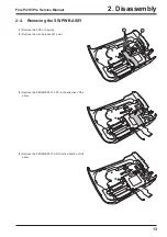
5
6
7
Hook
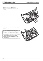
(5) Remove the 3 screws (BT2M 1.7 x 4.0 B).
(6) Remove the REAR FRAME in the direction of the
arrow.
(7) Remove the SW PWB ASSY in the direction of the
arrow.
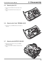
[Notes on assembling the SW PWB ASSY]
1. Check that the top edge of the SW PWB ASSY is
engaged with the hook on the R CABI ASSY side.
2. Take care to avoid inserting the FPC on an angle and
ensure that it is fully inserted before locking.
3. Ensure that there are no gaps between the CABI
after assembly.
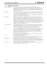
Summary of Contents for FinePix S3Pro
Page 27: ...27 3 Schematics FinePix S3Pro Service Manual 3 6 Circuit Diagrams 3 6 1 CCD BLOCK ...
Page 28: ...28 3 Schematics FinePix S3Pro Service Manual 3 6 2 DCDC BLOCK ...
Page 29: ...29 3 Schematics FinePix S3Pro Service Manual 3 6 3 IEEE1394 BLOCK ...
Page 30: ...30 3 Schematics FinePix S3Pro Service Manual 3 6 4 PROCESS BLOCK ...
Page 31: ...31 3 Schematics FinePix S3Pro Service Manual 3 6 5 CARD BLOCK 3 6 6 DCDC BLOCK CAMERA BODY ...
Page 32: ...32 3 Schematics FinePix S3Pro Service Manual 3 6 7 PARTNER CHIP BLOCK ...
Page 33: ...33 3 Schematics FinePix S3Pro Service Manual 3 6 8 PWON BLOCK ...
Page 34: ...34 3 Schematics FinePix S3Pro Service Manual 3 6 9 USB2 0 BLOCK ...
Page 35: ...35 3 Schematics FinePix S3Pro Service Manual 3 6 10 LCD BLOCK ...
Page 36: ...36 3 Schematics FinePix S3Pro Service Manual 3 6 11 SW BLOCK ...
Page 38: ...38 3 Schematics FinePix S3Pro Service Manual 3 7 2 MAIN PWB ASSY SIDE A ...
Page 39: ...39 3 Schematics FinePix S3Pro Service Manual SIDE B ...
Page 40: ...40 3 Schematics FinePix S3Pro Service Manual 3 7 3 SW PWB ASSY SIDE A SIDE B ...
Page 102: ...26 30 Nishiazabu 2 chome Minato ku Tokyo 106 8620 Japan FUJI PHOTO FILM CO LTD ...


