76
5. Inspection
FinePix S3Pro Service Manual
5-4.
Resolution Checking
<Step 1>
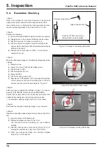
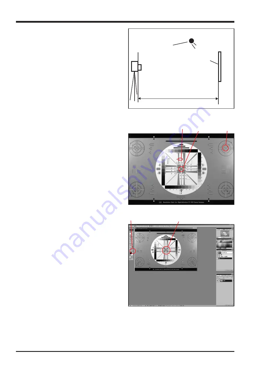
Refer to the settings for resolution checking in the figure at
right and set up the camera and the high-resolution chart.
Use a light source to illuminate the high-resolution chart so
that the surface brightness of the chart is 9.0 to 11.5 EV.
<Step 2>
Prepare the following:
(1) Insert a formatted 32 MB xD picture card into the camera.
(2) Supply power to the camera. (Batteries can be used.)
(3) Set the camera to “A” mode and switch it on.
(4) Set the camera on a tripod and point it directly at the
high-resolution chart (set at 90o horizontally and vertically
relative to the chart).
(5) Position the chart so that it is 1200 ± 5 mm from the
camera's F mount.
<Step 3>
Make the following changes to the default photography mode
settings:
(1) Select A mode.
(2) Select “Fine” and “12M” (4256 x 2848) mode.
(3) Set the flash to OFF.
(4) Set the aperture to F4.0.
(5) Select ISO 200.
(6) Set the focusing mode to “M”.
(7) Execute the “LIVE IMAGE :ON”. And, adjust the position
of the camera so that the chart displayed in the LCD
monitor may become the same angle as “Fig.5-4-2”.
<Step 4>
After you have completed the settings in steps 1 to 3 above,
Execute [LIVE IMAGE :ON] and execute [ENLARGE].
Adjust a focus ring so that a chart looks sharp.and press the
shutter button taking care to avoid any camera shake.
--> A resolution checking image (Fig. 5-4-2) is recorded.
<Step 5>
Download the resolution checking image to your computer.
<Step 6>
Resolution checking image enlargement procedure (Fig. 5-4-2
(2)).
(1) Open the image in Photoshop 5.0.
(2) Display the image as shown in Fig. 5-4-3.
The procedure varies depending on your software
settings.
(3) Use the zooming tool in the tool box (Fig. 5-4-3 (1)) to
enlarge the area shown in Fig. 5-4-2 (2) to 300%.
(4) When you enlarge the image, the centrally enlarged
image (Fig. 5-4-4) appears.
Distance of 1200+-5mm when
taking inspection photographs.
Fluorescent light stand
High-resolution chart
<Fig. 5-4-1> Setting for Inspecting Resolution
<Fig. 5-4-2> Resolution Check Image
(2)
(1)
(3)
(1)
(2)
<Fig. 5-4-3> Enlargement Using Photoshop
Summary of Contents for FinePix S3Pro
Page 27: ...27 3 Schematics FinePix S3Pro Service Manual 3 6 Circuit Diagrams 3 6 1 CCD BLOCK ...
Page 28: ...28 3 Schematics FinePix S3Pro Service Manual 3 6 2 DCDC BLOCK ...
Page 29: ...29 3 Schematics FinePix S3Pro Service Manual 3 6 3 IEEE1394 BLOCK ...
Page 30: ...30 3 Schematics FinePix S3Pro Service Manual 3 6 4 PROCESS BLOCK ...
Page 31: ...31 3 Schematics FinePix S3Pro Service Manual 3 6 5 CARD BLOCK 3 6 6 DCDC BLOCK CAMERA BODY ...
Page 32: ...32 3 Schematics FinePix S3Pro Service Manual 3 6 7 PARTNER CHIP BLOCK ...
Page 33: ...33 3 Schematics FinePix S3Pro Service Manual 3 6 8 PWON BLOCK ...
Page 34: ...34 3 Schematics FinePix S3Pro Service Manual 3 6 9 USB2 0 BLOCK ...
Page 35: ...35 3 Schematics FinePix S3Pro Service Manual 3 6 10 LCD BLOCK ...
Page 36: ...36 3 Schematics FinePix S3Pro Service Manual 3 6 11 SW BLOCK ...
Page 38: ...38 3 Schematics FinePix S3Pro Service Manual 3 7 2 MAIN PWB ASSY SIDE A ...
Page 39: ...39 3 Schematics FinePix S3Pro Service Manual SIDE B ...
Page 40: ...40 3 Schematics FinePix S3Pro Service Manual 3 7 3 SW PWB ASSY SIDE A SIDE B ...
Page 102: ...26 30 Nishiazabu 2 chome Minato ku Tokyo 106 8620 Japan FUJI PHOTO FILM CO LTD ...


