background image

Chapter 4 Disassembly/Assembly and Adjustment

4.2  Disassembly/Assembly

4-25

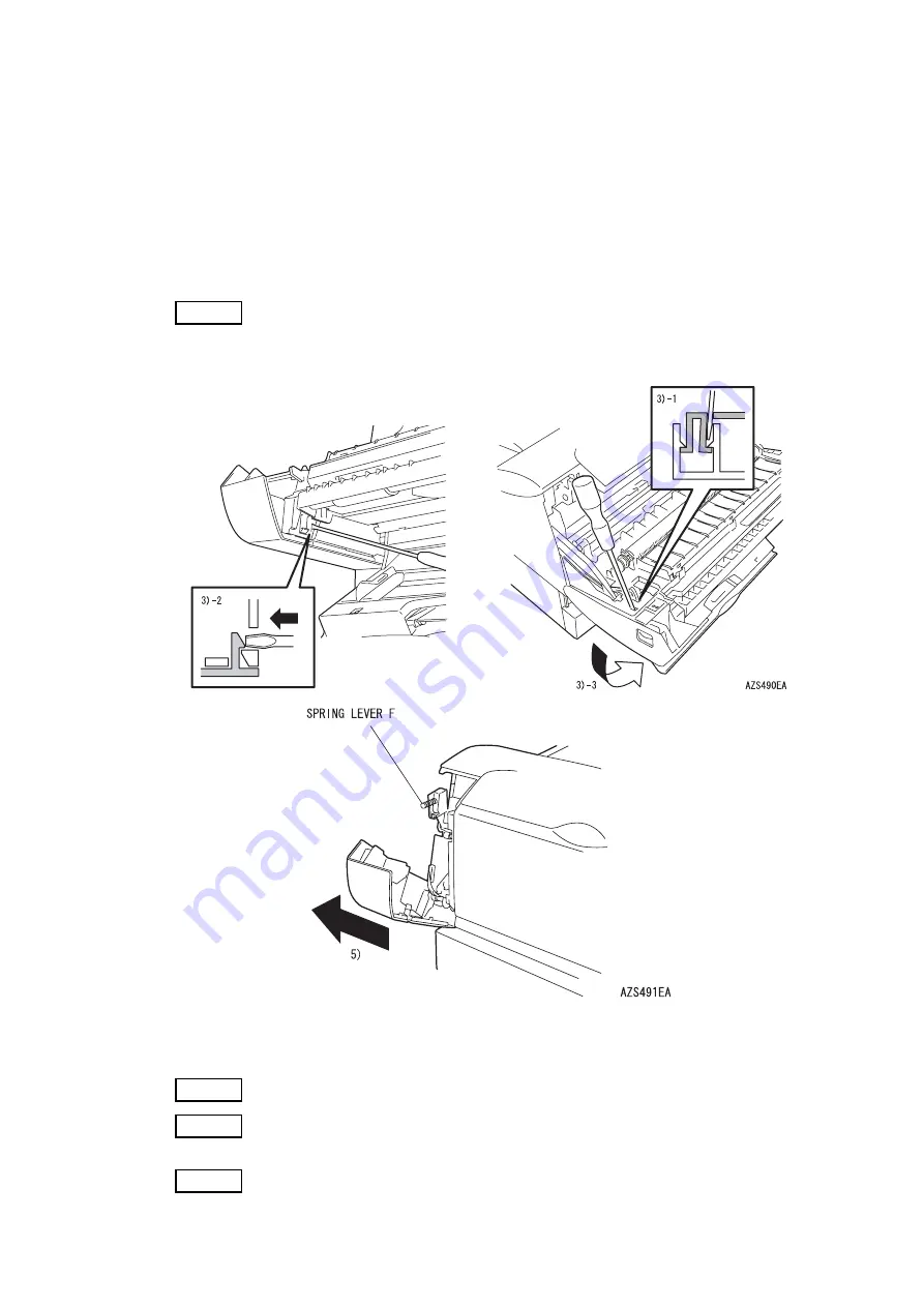
REP3.7  (SCC) COVER FRONT LEFT (PL3.1.31)

<Removal>

1) Pull the LEVER FRONT R (PL8.1.11) and LEVER FRONT L (PL8.1.12) concurrently toward you, 

open the COVER ASSY FRONT.

2) Open the TRAY ASSY FRONT CL (PL3.2.1).
3) Release the three hooks of the COVER FRONT LEFT and rotate the COVER FRONT LEFT.
4) Close the TRAY ASSY FRONT CL and the COVER ASSY FRONT.

NOTE

Be careful not to lose the SPRING LEVER F (PL8.1.25), because spring may be 
dropped by the next procedure.

5) Remove the COVER FRONT LEFT to the left.

<Replacement>

Perform the removal procedures in the reverse order.

NOTE

Be careful not to pinch the harness by the shaft of the cover.

NOTE

Attach the rib of COVER FRONT LEFT to the inside of the rib of the FRAME 
FRONT (PL8.1.2). (Refer to REP 3.6)

NOTE

After completion, confirm the LEVER FRONT L (PL8.1.12) movement.

Summary of Contents for DocuPrint 2050

Page 1: ...DocuPrint 2050 Service Manual 1st Edition KON001CA ...

Page 2: ... Modification Information When design changes or revisions relating to this service manual occur the overseas technical information or overseas service bulletin may be issued as supplementary information until such changes are accommodated in the updated version of this service manual CAUTION Important changes including revisions of spare part numbers and adjustment specifications must immediately...

Page 3: ...Company Name Department Name Telephone No Full Name Employee No ...

Page 4: ...apter 1 Service Call Procedure Chapter 2 Troubleshooting Chapter 3 Image Quality Troubleshooting Chapter 4 Disassembly Assembly and Adjustment Chapter 5 Parts List Chapter 6 General Chapter 7 Wiring Data Chapter 8 Accessories Not issued Chapter 9 BSD Block Schematic Diagram Not issued Chapter 10 Machine Overview ...

Page 5: ...Preface ...

Page 6: ...s Table of Contents 1 Getting to know the Service Manual Preface 2 2 How to use the Service Manual Preface 2 2 1 Contents of Manual Preface 2 2 2 Information on Updating Preface 3 3 Terms and Symbols Preface 4 4 Abbreviations Preface 5 ...

Page 7: ...l work and servicing procedures for the maintenance of the DocuPrint 2050 Chapter 2 Troubleshooting This chapter describes the troubleshooting procedures other than image quality troubleshooting of the DocuPrint 2050 It also describes how to use the diagnostics and some programs Chapter 3 Image Quality Troubleshooting This chapter describes the image quality troubleshooting procedures of DocuPrint...

Page 8: ...rocedure When the entire manual is revised 1st Edition on the front cover will be renewed to 1st Edition 2nd Edition 3rd Edition and so on When this manual is partially revised revisions will be sequentially indicated as Revision A Revision B Revision C etc All revised pages will be marked accordingly with Revision A Revision B Revision C and so on Revision Sidebar When any paragraph table or figu...

Page 9: ...tes a potentially hazardous situation such as injury or property damage if operators do not handle the machine correctly by disregarding the statement INSTRUCTION Indicates that the printer or its components may be damaged if the instructed procedure is not strictly observed NOTE Used to emphasize the procedure servicing and regulation REFERENCE Used to describe the technical terminology and suppl...

Page 10: ...trophotography ESS Electronic Sub System FDR Feeder FG Frame Ground H R Heat Roll HVPS High Voltage Power Supply I F Interface L Left L H Left Hand LD Laser Diode L P Low Paper LVPS Low Voltage Power Supply MCU Machine Main Control Unit MOT Motor MP Multi Purpose MSI Multi Sheet Inserter N F Normal Force N P No Paper OPC Organic Photo Conductor P H Paper Handling P R Pressure Roll PPM Prints Per M...

Page 11: ...Chapter 1 Service Call Procedure ...

Page 12: ...tents 1 1 Before Starting the Servicing 1 2 1 1 1 Safety 1 2 1 1 2 Other Things to Note 1 3 1 2 Servicing Call Procedure 1 4 1 3 TRIM Servicing 1 5 1 3 1 TRIM Servicing Procedure 1 5 1 3 2 Machine Consumables and Periodic Replacement Parts 1 6 1 3 3 TRIM Check List 1 7 ...

Page 13: ...ry such as panels and covers function properly Modifications that hinder the function of any safety devices are strictly prohibited 5 Installing and removing the parts The edge of parts and covers may be sharp take care not to touch them If the oil gets onto your hand wipe it off before getting on with the servicing When removing parts or cables do not pull them out by force but remove them slowly...

Page 14: ...f parts consumables replaced Make sure that the replaced parts or consumables as well as the packaging materials are collected back to the Service Center NOTE For the separation and processing methods for the collected items refer to the Common Technical Information No 2 138 for all machines If you have replaced the following consumables affix the U sticker for the recyclable parts to be handled a...

Page 15: ... 4 Feed paper from the respective trays and if necessary clean or replace the Feed Roll 5 Repair all the secondary problems 6 Perform TRIM servicing SM Call 1 Check the print quality 2 Feed paper from the respective trays and if necessary clean or replace the Feed Roll 3 Repair all the secondary problems 4 Perform TRIM servicing Final Actions 1 Check overall operation features 2 Check the machine ...

Page 16: ...t and check the print quality 2 Clean the interior of the machine Clean toner residues and paper powder etc in the paper delivery system Clean especially the operation section of the operator 3 Inspect parts that require periodic replacement consumables and replace them if necessary 4 Safety Precautions Check the connection of the power plug and any damage on the cord and the plug 5 Check the over...

Page 17: ...ing before replacing the machine consumables Machine Consumables Periodic Replacement Parts Consumables Product Code Life Drum toner cartridge CWAA0666 10KPV Consumables Replacement Interval Remarks FUSER ASSY 100KPV PAD ASSY RETARD 250 100KPV PAD ASSY RETARD TRAY 100KPV ROLL FEED ASSY TRAY 100KPV KIT REGISTRATION ASSY 100KPV KIT ROLL FEED ASSY 100KPV ROLL ASSY BTR 100KPV ...

Page 18: ... Roll A C Clean the paper dust and toner residue in the paper path and on the jam sensor Clean especially the operation section of the operator Check and clean the feed roll of the MSI 3 1 FUSER ASSY CL CH B C REP7 3 Check the H Roll and P Roll for scratches Replace FUSER ASSY CL CH if necessary 3 2 Drum toner cartridge B 10K Check visually Do not make direct contact 4 Safety Precautions B Make su...

Page 19: ...Chapter 2 Troubleshooting ...

Page 20: ...jam or pick error 2 15 FIP 1 6 REGI JAM Jam or pick error 2 16 FIP 1 7 Exit jam Jam or pick error 2 18 FIP 1 8 COVER TOP CL open Cover open 2 19 FIP 1 9 COVER ASSY FRONT open Cover open 2 20 FIP 1 10 Fuser error Fuser alarm 2 21 FIP 1 11 ROS error ROS or scanner motor alarm 2 22 FIP 1 12 Fan error Fan alarm 2 23 FIP 1 13 MOTOR ASSY MAIN alarm 2 24 FIP 1 14 BD alarm 2 25 FIP 1 15 Printing error 2 2...

Page 21: ...ERSION CHECK Diagnostic Codes 06 and 07 2 51 2 4 1 9 8 MAIN MOTOR TEST Diagnostic Codes 0C 2 52 2 4 1 9 9 PAPER FEEDER PICK TEST Diagnostic Code 0F 2 53 2 4 1 9 10 MSI CLUTCH TEST Diagnostic Code 0E 2 54 2 4 1 9 11 REGI ROLL CLUTCH TEST Diagnostic Code 14 2 55 2 4 1 9 12 SINGLE SELF PRINT TEST Diagnostic Code 15 2 56 2 4 1 9 13 CHARGE ROLL AC TEST Diagnostic Code 17 2 57 2 4 1 9 14 CHARGE ROLL DC ...

Page 22: ...indications and running at use of the diagnostic tool maintenance tool This system is configured so that troubleshooting is possible even when the diagnostic tool is not used so understand the fault analysis procedure before troubleshooting 2 1 Advancing Troubleshooting To effectively perform troubleshooting confirm the phenomenon and precheck the operation while referring to the FIP Fault Isolati...

Page 23: ...horizontal place 10 The papers conform to the specifications standard papers recommended 11 No error occurs during handling of the device 12 The parts to be replaced periodically are replaced for the specified number of prints 2 1 3 Notes on Work 1 Unless required be sure to disconnect the power cable AC WARNING While the power is turned on do not absolutely touch the powered parts The switch and ...

Page 24: ...N of CN1 and the minus side to 4PIN of P J3 8 To measure CN1 P J2 in the FIP refer to Section 5 Connection Wiring Diagram in Chapter 6 and check all the pins between the CN1 and P J2 9 The P J3 4PIN is necessarily set to SG signal ground or RTN return Therefore the FG frame ground SG signal ground is a connection type Confirm that the FG and SG are powered exactly and if necessary connect the minu...

Page 25: ...erring to Chapter 7 Wiring Data KON201CA Ask operator of the failure status Does operator operate correctly Y N Is a status code indicated Y N Y N Explain operator of correct operation procedures Repair referring to status code or message Determine corresponding image quality failure from contents of Chapter 3 and execute the procedure instructed Turn power off then on Is a status code indicated Y...

Page 26: ... 1 11 006 371 BD Alarm OFF BLK An error occurred on the printer 006 371 Attention required FIP 1 14 006 372 LASER Alarm OFF BLK An error occurred on the printer 006 372 Attention required FIP 2 2 007 340 Main Motor Alarm OFF BLK An error occurred on the printer 007 340 Attention required FIP 1 13 009 361 Drum toner cartridge Drum toner cartridge Error OFF BLK An error occurred on the printer 009 3...

Page 27: ...is not mounted or it is not mounted correctly Attach the Drum toner cartridge or insert and remove the Drum toner cartridge Paper size error The specified paper size is different from the size of a fed paper In case of MSI 1 The paper size specified with the ECP14 command differs from the size of the actually printed paper 2 The paper size sensed by the sensor differs from the size of the actually...

Page 28: ...the specified value Turn the power on and off Scanner motor alarm Scanner rotation error in ROS 1 The lock signal of the scanner motor remains set on 2 The lock signal of the scanner motor is not set off within the specified time Turn the power on and off FAN alarm FAN rotation error Turn the power on and off Main motor alarm Main motor error The Main Motor does not rotate or stop Turn the power o...

Page 29: ...rror damage transformation dirt or foreign object Major check parts PWBA MCU XFABK B PL9 1 25 Drum toner cartridge PL10 1 2 HARNESS ASSY CRUM PL4 1 12 Replace and reattach the parts There is a tool To step 2 There is no tool To step 3 2 HARNESS ASSY CRUM check Does the HARNESS ASSY CRUM function normally Select SENSOR SWITCH CHECK on the DIAGNOSTIC MODE MENU Replace the PWBA MCU XFABK B Replace th...

Page 30: ...ch the parts To step 2 2 Paper size check Is the paper size based on the specifications To step 3 Use the paper based on the specifications 3 Paper size sense mechanism check Does the paper size set to the Paper Cassette match the ON OFF combination of SWITCH P SIZE Go to FIP 2 3 SWITCH P SIZE error Replace the faulty part 4 ACTUATOR ASSY REGI check Does the ACTUATOR ASSY REGI run smoothly There i...

Page 31: ...WBA MCU XFABK B PL9 1 25 Replace and reattach the parts To step 2 2 Paper Cassette check Does the PLATE BOTTOM 250 lift normally at removal of the Paper Cassette To step 3 Replace the faulty part 3 ACTUATOR PAPER EMPTY check Does the ACTUATOR PAPER EMPTY run smoothly There is a tool To step 4 There is no tool Replace the SENSOR PHOTO Replace the ACTUATOR PAPER EMPTY 4 SENSOR PHOTO check Does the S...

Page 32: ... check Is the paper size based on the specifications To step 4 Use the paper based on the specifications 4 Paper position check Does paper pass through the ACTUATOR ASSY REGI at occurrence of the error To step 9 There is a tool To step 5 There is no tool To step 6 5 FEED MOTOR ASSY check Does the FEED MOTOR ASSY rotate normally Select the MP PICK TEST 1ST PICK TEST on the DIAGNOSTIC MODE MENU To s...

Page 33: ...I check Does the ACTUATOR ASSY REGI run smoothly There is a tool To step 10 There is no tool Go to FIP 2 4 PWBA SENSOR error Replace the ACTUATOR ASSY REGI 10 REGI SENSOR check Does the REGI SENSOR function normally Select SENSOR SWITCH CHECK on the DIAGNOSTIC MODE MENU Replace the PWBA MCU XFABK B Go to FIP 2 4 PWBA SENSOR error ...

Page 34: ...o step 3 Use the paper based on the specifications 3 Does any paper remain in the ACTUATOR ASSY REGI Remove the paper There is a too To step 4 There is no tool To step 5 4 MOTOR ASSY MAIN check Does the MOTOR ASSY MAIN rotate normally Select MOTOR ASSY MAIN TEST on the DIAGNOSTIC MODE MENU To step 5 Go to FIP 2 7 GEAR ASSY error 5 ROLL ASSY FEED REAR rotation check Does the ROLL ASSY FEED REAR rot...

Page 35: ... the specifications 4 GEAR ASSY check Does the CLUTCH REGI ROLL A gear Drum toner cartridge gear gear in the GEAR ASSY for the FUSER ASSY CL CH of H R GEAR rotate normally To step 5 Replace the GEAR ASSY 5 ROLL ASSY REGI check Does the ROLL ASSY REGI and ROLL ASSY PRESS rotate normally There is a tool To step 6 There is no tool To step 7 Replace the REGISTRATION ASSY 6 CLUTCH REGI ROLL A check Doe...

Page 36: ...rotate normally To step 11 Replace the FUSER ASSY CL CH 11 Check of paper entry to ROLL ASSY EXIT Does paper normally enter between the ROLL ASSY EXIT of the FUSER ASSY CL CH and the pinch roll Execute the test printing for visual check To step 12 Replace the FUSER ASSY CL CH 12 SENSOR ACTUATOR check Does the SENSOR ACTUATOR run smoothly There is a tool To step 13 There is no tool Go to FIP 2 5 Se...

Page 37: ... FUSER ASSY CL CH PWBA MCU XFABK B PL9 1 25 Replace and reattach the parts To step 2 2 Does paper remain in the SENSOR ACTUATOR Remove the paper To step 3 3 Check of paper entry to the ROLL ASSY EXIT Does paper normally enter between the ROLL ASSY EXIT of the FUSER ASSY CL CH and the pinch roll Execute the test printing for visual check To step 4 Replace the FUSER ASSY CL CH 4 SENSOR ACTUATOR chec...

Page 38: ...TERLOCK SWITCH push check When closing the COVER TOP CL turn the INTERLOCK SWITCH ON When opening the COVER TOP CL is the INTERLOCK SWITCH turned OFF There is a tool To step 3 There is no tool To step 4 Replace the faulty part 3 INTERLOCK SWITCH check Does the INTERLOCK SWITCH function normally Select SENSOR SWITCH CHECK on the DIAGNOSTIC MODE MENU Replace the PWBA MCU XFABK B To step 4 4 INTERLOC...

Page 39: ... push check When closing the COVER ASSY FRONT is the INTERLOCK SWITCH turned ON When opening the COVER ASSY FRONT is the INTERLOCK SWITCH turned OFF There is a tool To step 3 There is no tool To step 4 Replace the faulty part 3 INTERLOCK SWITCH check Does the INTERLOCK SWITCH function normally Select SENSOR SWITCH CHECK on the DIAGNOSTIC MODE MENUS Replace the PWBA MCU XFABK B To step 4 4 INTERLOC...

Page 40: ...een J302 FUSER ASSY CL CH To step 3 Replace the HARNESS ASSY FUSER 3 LVPS 230 check Is 5VDC applied to the J108 4PIN J108 6PIN Is 24VDC applied to the J108 3PIN J108 5PIN There is a tool To step 4 There is no tool To step 5 Replace the LVPS 230 4 FUSER ASSY CL CH temperature check Is the FUSER ASSY CL CH temperature normal Select FUSER TEMPERATURE CHECK on the Diagnostic Mode menu for this check T...

Page 41: ...U XFABK B PL9 1 25 Drum toner cartridge PL10 1 2 LVPS 230 PL9 1 5 Replace and reattach the parts There is a tool To step 2 There is no tool To step 3 2 Scanner Motor check Does the scanner motor rotate at test printing in the Test Pattern Mode Check the rotation noise To FIP 2 2 ROS ASSY fault To step 3 3 LD relay cable and Scanner Motor relay cable connection check Are the LD relay cable and Scan...

Page 42: ...FAN check Does the FAN or FAN ASSY rotate at power on To step 4 There is a tool To step 3 There is no tool To step 4 3 FAN check Does the FAN or FAN ASSY run normally Select FAN MOTOR HIGH SPEED TEST or FAN MOTOR STOP TEST on the Diagnostic Mode Menu Replace the FAN or FAN ASSY To step 4 4 FAN power check Is 24VDC applied to the J104 1PIN J104 3PIN Is 24VDC applied to the J103 1PIN J103 3PIN To st...

Page 43: ...7 GEAR ASSY error To step 3 3 GEAR ASSY check Does each gear in the GEAR ASSY rotate smoothly Remove the FUSER ASSY CL CH and the Drum toner cartridge rotate the gears by hands and visually check that the gears function normally To step 4 Replace the GEAR ASSY 4 FUSER ASSY CL CH check Does each gear or roll of the FUSER ASSY CL CH rotate smoothly Remove the FUSER ASSY CL CH rotate the gears by han...

Page 44: ...transformation dirt or foreign object Major check parts FFC VIDEO PL9 1 28 PWBA MCU XFABK B PL9 1 25 ESS PWB PL9 1 21 Replace and reattach the parts To step 2 2 FFC VIDEO check Does the J107 CN4 connect normally To step 3 Replace the FFC VIDEO 3 PWBA MCU XFABK B replacement check Does this error recur after the defective PWBA MCU XFABK B is replaced with a new one Replace the ESS PWB Action comple...

Page 45: ... AZUSA HVPS PL9 1 6 LVPS 230 PL9 1 5 Replace and reattach the parts To step 2 2 Is no printing performed To step 4 To step 3 3 Is the device reset during printing Go to FIP 2 9 Noise To step 4 4 PWBA MCU XFABK B replacement check Does this error recur after the defective PWBA MCU XFABK B is replaced with a normal one To step 5 Action completed 5 Interface Cable check Does this error recur after th...

Page 46: ...h as use of parts in different specifications attachment error damage transformation dirt or foreign object Major check parts PWBA MCU XFABK B PL9 1 25 LVPS 230 PL9 1 5 Replace and reattach the parts To step 2 2 LVPS 230 check Is 5VDC applied to the J108 4PIN J108 3PIN Is 24VDC applied to the J108 6PIN J108 5PIN To step 3 Replace the LVPS 230 3 DC Cable check Is the LVPS 230 P108 connect normally ...

Page 47: ...J106 4PIN To step 5 To step 3 3 PWBA MCU XFABK B continuity check Are the J105 1PIN ROS ASSY 8PIN and J106 1PIN ROS ASSY connected normally To step 4 Replace the ROS ASSY 4 PWBA MCU XFABK B LVPS 230 check Is the harness between the PWBA MCU XFABK B and LVPS 230 connected normally To step 5 Replace the LVPS 230 5 Scan Motor Drive check Is 0VDC applied to the J105 3PIN J105 2PIN at power on Replace ...

Page 48: ...e transformation dirt or foreign object Major check parts LVPS 230 PL9 1 5 HARNESS ASSY PH PL5 1 30 SWITCH P SIZE PL5 1 29 PWBA MCU XFABK B PL9 1 25 Replace and reattach the parts To step 2 2 HARNESS ASSY PH check Is the J100 J1002 connected normally To step 3 Replace the HARNESS ASSY PH 3 SWITCH P SIZE check Is the J100 SWITCH P SIZE connected normally Replace the PWBA MCU XFABK B Replace the SWI...

Page 49: ...rmation dirt or foreign object Major check parts PWBA SENSOR PL4 1 17 CABLE SENSOR PL9 1 9 PWBA MCU XFABK B PL9 1 25 Replace and reattach the parts To step 2 2 CABLE SENSOR check Is the CN101 J101 connected normally To step 3 Replace the CABLE SENSOR 3 PWBA MCU XFABK B replacement check Does this error recur after the defective PWBA MCU XFABK B is replaced with a normal one Replace the PWBA SENSOR...

Page 50: ...ASSY CL CH FUSER ASSY CL CH PL7 1 15 PWBA MCU XFABK B PL9 1 25 Eject Sensor Cable mounted on the FUSER ASSY CL CH HARNESS ASSY FUSER PL9 1 7 LVPS 230 PL9 1 5 Replace and reattach the parts To step 2 2 Sensor Exit power check Is 5VDC applied to the CN103 3PIN CN103 2PIN To step 3 Go to FIP 2 1 LVPS 230 error 3 PAPER EXIT Sense Signal power check Is 5VDC applied to the CN103 1PIN CN103 2PIN To step ...

Page 51: ...arts CLUTCH REGI ROLL A PL4 1 42 PWBA SENSOR PL4 1 17 Replace and reattach the parts To step 2 2 CLUTCH REGI ROLL A power check Is 24VDC applied to the CN102 2PIN CN101 12PIN To step 3 Replace the PWBA SENSOR 3 CLUTCH REGI ROLL A ON signal check Is 0VDC applied to the CN102 1PIN CN101 12PIN at CLUTCH REGI ROLL A ON and 24VDC at CLUTCH REGI ROLL A OFF Replace the CLUTCH REGI ROLL A To step 4 4 CLUT...

Page 52: ...PL9 1 25 Replace and reattach the parts To step 2 2 GEAR ASSY MOTOR ASSY MAIN power check Is 5VDC applied to the J1090 3PIN J1090 4PIN Disconnect the Drum toner cartridge and turn on the INTERLOCK SWITCH for check To step 3 Replace the PWBA MCU XFABK B 3 HARNESS ASSY MOTOR MAIN check Is the J109 J1090 connected normally To step 4 Replace the HARNESS ASSY MOTOR MAIN 4 PWBA MCU XFABK B replacement c...

Page 53: ...transformation dirt or foreign object Major check parts AZUSA HVPS PL9 1 6 CABLE HV PL9 1 8 PWBA MCU XFABK B PL9 1 25 Replace and reattach the parts To step 2 2 CABLE HV check Is the CN201 J201 connected normally To step 3 Replace the CABLE HV 3 PWBA MCU XFABK B replacement check Does this error recur after the defective PWBA MCU XFABK B is replaced with a normal one Replace the AZUSA HVPS Action ...

Page 54: ...E HV 1 check Is the PLATE HV 1 transformed Otherwise does the plate HV 1 normally come into contact with the Drum toner cartridge To step 6 Replace the PLATE HV 1 6 FRAME ASSY FRONT check Is the electric path in the FRAME ASSY FRONT connected normally To step 7 Replace the FRAME ASSY FRONT 7 REGISTRATION ASSY check Is the electric path in the REGISTRATION ASSY connected normally To step 8 Replace ...

Page 55: ...ally replaced parts as required 3 Print out a few papers and confirm that no error occurs 4 Eliminate foreign objects in the PLATE DT SAW paper transport route paper transport roll and so on Then clean the dirty parts with a brush or dry cloth NOTE When there are too dirty parts clean them with a wet cloth then wipe off with a dry cloth In this case take care that the parts are not damaged 5 Clean...

Page 56: ...cifications NOTE This manual describes the operation indication and operations at use of the dialog commander maintenance tool If the system has a controller or diagnostic function in a PC use it preferentially 2 4 1 Outline of Operation 2 4 1 1 Diagnostic Tool Components CD ROM for activating Diagnostic And Adjustment Software DIAG I F BOARD Centronics parallel printer cable Use Environment DOS V...

Page 57: ... hook of DIAG I F BOARD to the frame as shown in illustration 5 Connect the PC to the DIAG I F BOARD with a parallel cable 2 4 1 3 Activating 1 Execute the set up Setup exe of diagnostic tool from the CD ROM 2 Double click the Diag the Diagnostic and Software is activated The device is then placed into the power on ready state 3 Turn the device power on CAUTION In case of Windows2000 or XP install...

Page 58: ...odes use the Main Menu SENSOR SWITCH CHECK ROM MINOR VERSION CHECK PAPER FEEDER PICK TEST REGI ROLL CLUTCH TEST CHARGE ROLL AC TEST STOP ALL TEST FUSER TEMPERATURE CHECK MAIN MOTOR TEST MSI CLUTCH TEST SINGLE SELF PRINT TEST CHARGE ROLL DC TEST DEVELOPER BIAS DC TEST TRANSFER ROLL TEST FAN MOTOR STOP TEST DEVELOPER BIAS AC TEST TRANSFER ROLL TEST FAN MOTOR HIGH SPEED TEST DIAGNOSTIC MODE MENU MAIN...

Page 59: ...rs Wait until the device power is turned on CAUTION If the screen does not change at power on the loose connection contact error or installed by the privilege of Non Administrators in case of Windows2000 or XP is thought After power on the screen appears Confirm the version of the software press the Page Down key or Enter key to go to the next page Version ...

Page 60: ... How to use PC Diag 2 41 Select each item Proceed to the Main Menu Install instructions for Diagnostic Interface Use the up arrow and down arrow keys to select a desired item and press the Enter key The selected item is highlighted ...

Page 61: ...ocedure of connecting the PC and the device Confirm the items press the Esc The Main Menu is displayed 2 4 1 7 Main Menu Select each item on the Main Menu Test Pattern Mode Diagnostic Mode LPT Port Setting Mode Use the up arrow and down arrow keys to select a desired item and press the Enter key The selected item is highlighted ...

Page 62: ...EST PATTERN MODE MENU 2 4 1 8 1 Functions The Test Pattern Mode is used to print out the test patterns built in the device for operation check The test printing self patterns are as follows Number of horizontal solid lines A3P 41 B4P 35 LTL 20 A4L 20 B5L 17 A5L 13 ...

Page 63: ... Diag 2 44 2 4 1 8 2 Entering TEST PATTERN MODE MENU Select Test Pattern Mode on the Main Menu Press the Page Down key or the Enter key to go to the next page The TEST PATTERN MODE screen is displayed The feeder for test printing is displayed A ...

Page 64: ...rinting starts Warning Confirm that the covers are attached normally at printing Then check whether paper is supplied from a Paper Feeder and feed paper from a Feeder having papers To end this processing press the End or Esc key To return to the Main Menu press the Esc key A B When the paper is not set the NO PAPER is displayed ...

Page 65: ...rface Specifications Diagnostic code Operation to be executed 00 Stop of all diagnostic operation or stop of self test continuance printing 01 Sensor input test 03 Fuser temperature b7 to b4 04 Fuser temperature b3 to b0 06 ROM minor version upper 07 ROM minor version lower 0C Main motor operation check 1 0E MSI pick operation check 1 0F PAPER FEEDER pick operation check 1 14 Registration clutch o...

Page 66: ...screen enter a desired test parameter Stop All Tests Main Motor Test Paper Feeder Pick Test MSI Clutch Test or Regi Roll Clutch Test and others for which explanation is displayed A test that requires machine operation functions only for a specified time 3 sec Main Motor Test Paper Feeder Pick Test MSI Clutch Test Regi Roll Clutch Test Charge AC Test Charge DC Test Developer Bias AC Test Developer ...

Page 67: ...erations even when the screen returns to the Main Menu after the Diagnostic Mode ends Use the up arrow down arrow left arrow and right arrow keys to select Stop All Tests from DIAGNOSTIC MODE MENU Press the Enter key Press the Enter key and stop the all diagnostic The state of operation is displayed on the lower right of screen Press the Esc key return to the DIAGNOSTIC MODE MENU ...

Page 68: ...vice Use the up arrow down arrow left arrow and right arrow keys to select Sensor Switch Check from DIAGNOSTIC MODE MENU Press the Enter key When the change of the sensor is sensed the numeric value on the lower right of the screen Sensor Check is counted up When the count reaches 15 it returns to 0 and count up restarts Press the Esc key return to the DIAGNOSTIC MODE MENU ...

Page 69: ...ture is displayed on the lower right of the screen in hexadecimal notation Refer to the conversion table on the displayed screen to obtain the actual temperature Then press the Page Up key the screen returns to the preceding screen Pressing the Esc key returns to the Diagnostic Mode Menu Temperature code list FUSER temp temp code HEX FUSER temp temp code HEX 50 C F3 150 C 77 60 C EE 160 C 68 70 C ...

Page 70: ... VERSION CHECK Diagnostic Codes 06 and 07 This function displays the version of the firmware Use the up arrow down arrow left arrow and right arrow keys to select ROM Miner Version Check Then press the Enter key to execute Press the Esc key return to the DIAGNOSTIC MODE MENU ...

Page 71: ... down arrow left arrow and right arrow keys to select Main Motor Test and press the Enter key the main motor runs for a predetermined time CAUTION When the main motor runs the roller also rotates Take care that fingers are not caught The state of operation is displayed on the lower right of screen Press the Esc key return to the DIAGNOSTIC MODE MENU ...

Page 72: ...e up arrow down arrow left arrow and right arrow keys to select Paper Feeder Pick Test and press the Enter key the Motor operation runs for a predetermined time CAUTION When the Pick Motor runs the roller also rotates Take care that fingers are not caught The state of operation is displayed on the lower right of screen Press the Esc key return to the DIAGNOSTIC MODE MENU ...

Page 73: ...hecks Clutch operation for MSI feeding Use the up arrow down arrow left arrow and right arrow keys to select MSI Clutch Test and press the Enter key the clutch operation runs for a predetermined time The state of operation is displayed on the lower right of screen Press the Esc key return to the DIAGNOSTIC MODE MENU ...

Page 74: ...rrow down arrow left arrow and right arrow keys to select Regi Roll Clutch Test and press the Enter key the solenoid operation runs for a predetermined time CAUTION When the Main Motor runs the Regi Roll also rotates Take care that fingers are not caught The state of operation is displayed on the lower right of screen Press the Esc key return to the DIAGNOSTIC MODE MENU ...

Page 75: ...e for operation check Use the up arrow down arrow left arrow and right arrow keys to select Single Self Print Test and press the Enter key the screen below appears Then press the Enter key again the system checks whether paper exists from Feeder and feeds papers from a Feeder having papers then starts printing Press the Esc key return to the DIAGNOSTIC MODE MENU ...

Page 76: ...that you do not receive an electric shock because the AC voltage is high Use the up arrow down arrow left arrow and right arrow keys to select Charge AC Test and press the Enter key the screen below appears Then press the Enter key again to execute this processing The state of operation is displayed on the lower right of screen Press the Esc key return to the DIAGNOSTIC MODE MENU ...

Page 77: ...that you do not receive an electric shock because the DC voltage is high Use the up arrow down arrow left arrow and right arrow keys to select Charge DC Test and press the Enter key the screen below appears Then press the Enter key again to execute this processing The state of operation is displayed on the lower right of screen Press the Esc key return to the DIAGNOSTIC MODE MENU ...

Page 78: ... care that you do not receive an electric shock because the AC voltage is high Use the up arrow down arrow left arrow and right arrow keys to select Developer Bias AC Test and press the Enter key the screen below appears Then press the Enter key again to execute this processing The state of operation is displayed on the lower right of screen Press the Esc key return to the DIAGNOSTIC MODE MENU ...

Page 79: ... care that you do not receive an electric shock because the DC voltage is high Use the up arrow down arrow left arrow and right arrow keys to select Developer Bias DC Test and press the Enter key the screen below appears Then press the Enter key again to execute this processing The state of operation is displayed on the lower right of screen Press the Esc key return to the DIAGNOSTIC MODE MENU ...

Page 80: ...at you do not receive an electric shock because the minus voltage is high Use the up arrow down arrow left arrow and right arrow keys to select Transfer Roll Test and press the Enter key the screen below appears Then press the Enter key again to execute this processing The state of operation is displayed on the lower right of screen Press the Esc key return to the DIAGNOSTIC MODE MENU ...

Page 81: ...at you do not receive an electric shock because the plus voltage is high Use the up arrow down arrow left arrow and right arrow keys to select Transfer Roll Test and press the Enter key the screen below appears Then press the Enter key again to execute this processing The state of operation is displayed on the lower right of screen Press the Esc key return to the DIAGNOSTIC MODE MENU ...

Page 82: ... Motor at high speed Use the up arrow down arrow left arrow and right arrow keys to select Fan Motor High Speed Test and press the Enter key the screen below appears Then press the Enter key again to execute this processing The state of operation is displayed on the lower right of screen Press the Esc key return to the DIAGNOSTIC MODE MENU ...

Page 83: ...he Fan Motor Use the up arrow down arrow left arrow and right arrow keys to select Fan Motor Stop Test and press the Enter key the screen below appears Then press the Enter key again to execute this processing The state of operation is displayed on the lower right of screen Press the Esc key return to the DIAGNOSTIC MODE MENU ...

Page 84: ... varies depending on the PC used Refer to the instruction manual of the model used or switch the LPT port to try this processing until the selected address matches the model used 2 4 1 10 2 Entering LPT PORT SETTING MENU Select LPT Port Setting Menu on the Main Menu Use the up arrow and down arrow keys to select a desired item and press the Enter key Pressing the Esc key returns to the Main Menu ...

Page 85: ...Chapter 3 Image Quality Troubleshooting ...

Page 86: ...ERN PRINT 3 13 3 5 Image Quality FIP 3 14 FIP P1 All white 3 14 FIP P2 All black 3 15 FIP P3 Thin printing or paper transport direction missing 3 16 FIP P4 Horizontal missing thin toner on non print part or whitened character 3 17 FIP P5 Obscure printing 3 18 FIP P6 Determined position missing 3 19 FIP P7 Cyclic missing 3 20 FIP P8 Cyclic toner on non print part 3 21 FIP P9 Toner at determined pos...

Page 87: ...he case where the Diag tools are not used You can correct troubles according to these troubleshooting procedures after understanding them well 3 1 Image Troubleshooting KON301CA Replace Drum toner cartridge then FUSER ASSY The trouble is restored End End The trouble is restored Carry out the corresponding troubleshooting Start Teat Printing Is there a corresponding FIP No Yes No No Yes Yes ...

Page 88: ...urs print on paper of A3 or A4 size in order to judge and understand the trouble precisely and take proper remedy steps Utilize the image quality troubleshooting correction table depending on the trouble for efficient troubleshooting If the trouble cannot be corrected according to the image quality troubleshooting check the trouble after replacing the Major check parts specified for the Initial ch...

Page 89: ...error Dirty or damaged ROLL BTR Dirty Pressure Roller 4 Cyclic horizontal streak horizontal line Approx 44mm 48mm or 52mm cycle Approx 55mm cycle Approx 95mm cycle Approx 78mm cycle Dirty or damaged Developing Roller dirty Charge Roller or Drum toner cartridge error Dirty ROLL BTR or defective Trans Roller OPC drum damage or Drum toner cartridge error cleaning error FUSER ASSY CL CH Heat Roller da...

Page 90: ...uality Specifications 3 5 3 2 Image Quality Specifications 3 2 1 Print Guaranteed Area KON302CA 5mm 5mm 5mm 5mm 420mm 297mm MSI run 410mm 287mm Guaranteed printing area 5mm 5mm 5mm 5mm 420mm 297mm 250 sheet tray run 410mm 287mm Guaranteed printing area ...

Page 91: ...g 3 3 Print Alignment 3 6 3 3 Print Alignment 3 3 1 Lead edge registration Measure how the print out on paper is dislocated from the reference position Measure how the reference position is dislocated 15mm from the paper edge in the center ...

Page 92: ...Chapter 3 Image Quality Troubleshooting 3 3 Print Alignment 3 7 3 3 2 Side edge registration Measure how the reference position is dislocated 148 5mm from the paper left end in the center ...

Page 93: ...Chapter 3 Image Quality Troubleshooting 3 3 Print Alignment 3 8 3 3 3 Skew Measure the oblique paper feeding Measure in the 245mm range on the horizontal line at the end ...

Page 94: ...hooting 3 3 Print Alignment 3 9 3 3 4 Right angle Measure the right angle to reduce the inclination of the ROS and OPC Measure a horizontal error at the logical value 90 degrees apart 195mm from the center point on the horizontal line ...

Page 95: ...ing 3 3 Print Alignment 3 10 3 3 5 Linearity Confirm the performance of the paper feeding and the ROS in the linearity of vertical line horizontal line and diagonal line Measure the distance of the line between A and B line that passes C ...

Page 96: ...ent 3 11 3 3 6 Horizontal level Measure the difference between the feeding speeds on the left and right of paper as the horizontal level Measure the difference of the distance between vertical lines separate 245mm horizontally from the reference length 390mm ...

Page 97: ...12 3 3 7 Magnification Measure the warping of vertical paper feeding direction and warping of horizontal ROS Measure the actual line on the center of paper and calculate the ratio to the reference line Vertical reference line 390mm Horizontal reference line 245mm ...

Page 98: ...The Test Pattern Print is used to print out the test patterns built in the device for operation check The printing is executed by the PC diagnostic refer to the Chapter 2 The test printing self patterns are as follows Number of horizontal solid lines A3P 41 B4P 35 LTL 20 A4L 20 B5L 17 A5L 13 ...

Page 99: ...0 1 2 ROS ASSY PL10 1 1 PWBA MCU PL9 1 25 Item Check Action at occurrence of error 1 Drum toner cartridge error 1 Does toner remain in the Drum toner cartridge Replace the Drum toner cartridge 2 Drum toner cartridge error 2 Is the toner seal pulled out from the Drum toner cartridge Pull out the toner seal of the Drum toner cartridge 3 ROS ASSY connection error Is the connector normally connected t...

Page 100: ...formation dirt or foreign object Major check parts AZUSA HVPS PL9 1 6 ROS ASSY PL10 1 1 Drum toner cartridge PL10 1 2 Item Check Action at occurrence of error 1 High pressure spring error Is the high pressure spring transformed or damaged Check FIP 2 8 AZUSA HVPS error 2 ROS ASSY error Does the ROS ASSY run normally Check FIP 2 2 ROS ASSY error 3 Drum toner cartridge error Doesn t this error recur...

Page 101: ...occurrence of error 1 Drum toner cartridge error 1 Is the toner seal from the Drum toner cartridge Pull out the toner seal from the Drum toner cartridge 2 ROLL ASSY BTR attachment error Is the ROLL ASSY BTR attached securely Reattach the ROLL ASSY BTR 3 ROLL BTR error Does the current flow to the ROLL BTR If the current flows replace the ROS ASSY otherwise check the conductive state When the condu...

Page 102: ...fications attachment error damage transformation dirt or foreign object Major check parts Drum toner cartridge PL10 1 2 ROLL BTR PL8 1 14 FUSER ASSY CL CH PL7 1 15 Item Check Action at occurrence of error 1 Measure a cyclic interval Is the cyclic interval random 55mm or 78mm For 55mm check whether the ROLL BTR is attached correctly or replace the ROLL BTR For 78mm replace the FUSER ASSY CL CH 2 Dr...

Page 103: ...specifications attachment error damage transformation dirt or foreign object Major check parts Drum toner cartridge PL10 1 2 ROS ASSY PL10 1 1 Item Check Action at occurrence of error 1 Drum toner cartridge error Doesn t this error recur after the defective Drum toner cartridge is replaced with a new one Replace the Drum toner cartridge 2 ROS ASSY error Does the ROS ASSY run normally Check FIP 2 2...

Page 104: ...arts in different specifications attachment error damage transformation dirt or foreign object Major check parts CASSETTE ASSY 250 CL PL2 1 1 Item Check Action at occurrence of error 1 Is the specified paper used Use the specified paper 2 Is the paper stored in an appropriate place Improve the paper storage environment 3 Does papers remain set in the paper cassette for a long time Supply new paper...

Page 105: ... Are there errors such as use of parts in different specifications attachment error damage transformation dirt or foreign object Major check parts Drum toner cartridge PL10 1 2 ROLL BTR PL8 1 14 FUSER ASSY CL CH PL7 1 15 Item Check Action at occurrence of error 1 Measure the cyclic interval For 95mm 44mm 48mm or 52mm replace the Drum toner cartridge For 55mm replace the ROLL BTR For 78mm replace t...

Page 106: ...on print parts This occurs cyclically at the same intervals Initial check Are there errors such as use of parts in different specifications attachment error damage transformation dirt or foreign object Major check parts Drum toner cartridge PL10 1 2 Item Check Action at occurrence of error 1 Measure the cyclic interval For 95mm 44mm or 48mm replace the Drum toner cartridge ...

Page 107: ...ations attachment error damage transformation dirt or foreign object Major check parts CASSETTE ASSY 250 CL PL2 1 1 ROLL BTR PL8 1 14 Item Check Action at occurrence of error 1 Is toner detected in the lower part Clean the inside of the device 2 Is the toner detected in the edge at the end of paper Check whether the ROLL BTR is attached normally Clean the inside of the device 3 Is the specified pa...

Page 108: ... toner at random Initial check Are there errors such as use of parts in different specifications attachment error damage transformation dirt or foreign object Major check parts FUSER ASSY CL CH PL7 1 15 Item Check Action at occurrence of error 1 FUSER ASSY CL CH error Is toner detected before the FUSER ASSY CL CH Replace the FUSER ASSY CL CH Clean the inside of the device ...

Page 109: ... use of parts in different specifications attachment error damage transformation dirt or foreign object Major check parts FUSER ASSY CL CH PL7 1 15 Item Check Action at occurrence of error 1 Is paper set correctly Set paper correctly 2 Is the specified paper used Use the specified paper 3 FUSER ASSY CL CH attachment error Is the FUSER ASSY CL CH attached securely Reattach the FUSER ASSY CL CH ...

Page 110: ...ction at occurrence of error 1 Is the humidity too low Adjust the humidity 2 Is the specified paper used Use the specified paper 3 Is paper stored in an appropriate place Improve the paper storage environment 4 Is the PLATE DT SAW dirty Clean the PLATE DT SAW 5 Is the voltage applied to the PLATE DT SAW Check the contacts of the high voltage terminals When they are not normal repair them When they...

Page 111: ...k Are there errors such as use of parts in different specifications attachment error damage transformation dirt or foreign object Major check parts FUSER ASSY CL CH PL7 1 15 Item Check Action at occurrence of error 1 Does this error occur after the inside of the device is cleaned Check the pressure roller of the FUSER ASSY CL CH If it is dirty replace the FUSER ASSY CL CH ...

Page 112: ...0 CL PL2 1 1 Item Check Action at occurrence of error 1 Is paper set correctly Set paper correctly 2 Is the specified paper used Use the specified paper 3 Is paper stored in an appropriate place Improve the paper storage environment 4 Is not paper wound round the pressure roller of the FUSER ASSY CL CH Remove the FUSER ASSY CL CH and pull out the wound paper 5 FUSER ASSY CL CH attachment error Is ...

Page 113: ...k Action at occurrence of error 1 Is the ream of papers in the specified range Set papers in the specified range 2 Is the heater of the FUSER ASSY CL CH turned on When the heater is turned on replace the FUSER ASSY CL CH otherwise check whether the heater of the FUSER ASSY CL CH is conductive If it is conductive replace the AZUSA HVPS If it is not conductive replace the FUSER ASSY CL CH 3 Does thi...

Page 114: ...Chapter 4 Disassembly Assembly and Adjustment ...

Page 115: ...REP3 1 FRONT UNIT Reference Only 4 17 REP3 2 FRAME ASSY ROLL FEED TRAY PL3 1 10 4 19 REP3 3 SCC CLUTCH ROLL FEED TRAY PL3 1 20 4 20 REP3 4 ROLL FEED ASSY TRAY PL3 1 21 4 22 REP3 5 PAD ASSY RETARD TRAY PL3 1 23 4 23 REP3 6 SCC COVER FRONT RIGHT PL3 1 30 4 24 REP3 7 SCC COVER FRONT LEFT PL3 1 31 4 25 REP3 8 TRAY ASSY FRONT CL PL3 2 1 4 26 REP3 9 PLATE ASSY BTM TRAY PL3 2 3 4 27 REP4 Paper Feeder 4 2...

Page 116: ...7 1 10 4 55 REP8 Paper Transportation 4 56 REP8 1 LEVER FRONT R PL8 1 11 4 56 REP8 2 LEVER FRONT L PL8 1 12 4 57 REP8 3 ROLL ASSY BTR PL8 1 13 4 58 REP8 4 PLATE DT SAW PL8 1 4 CHUTE TRANS PL8 1 9 4 59 REP8 5 SPRING BTR PL8 1 6 BEARING BTR PL8 1 7 4 61 REP8 6 FRAME ASSY FRONT PL8 1 1 4 62 REP8 7 HARNESS ASSY HV BTR PL8 1 5 SCC HARNESS ASSY HV DT PL8 1 8 SCC HARNESS ASSY HV TRANS PL8 1 10 4 64 REP9 ...

Page 117: ...a spare part with no procedural instructions check the mounting status well before removal NOTE As a rule options shall be removed If there is no problem however they may be left mounted 4 1 1 Before Work Turn the power off and unplug the power cable For work around the FUSER ASSY CL CH wait until the FUSER ASSY CL CH and its ambient temperatures go down well Handle parts with great care An excess...

Page 118: ...ed from the front of the equipment A procedure describes the mounting position color characteristics and shank length of a screw REP X Y in the middle or at the end of a sentence in a procedure means that a work procedure related to Removal Replacement X Y is given Figure X Y at the end of a sentence in a procedure means that a reference illustration for Removal Replacement X Y is shown Z in an il...

Page 119: ... FFC OPP CL PL1 1 21 in the procedure below 3 Remove the COVER ASSY TOP CL with the FFC OPP CL REP1 4 4 Remove the four screws 1 pc top front gold tap 8mm 3 pcs gold with washer 8mm securing the COVER SIDE LEFT CL 5 Open the COVER SIDE LEFT CL to left and pull the cover upward to remove Replacement Perform the removal procedures in the reverse order CAUTION When replacing the COVER SIDE LEFT CL be...

Page 120: ...AUTION Be careful not to damage the FFC OPP CL PL1 1 21 in the procedure below 3 Remove the COVER ASSY TOP CL with the FFC OPP CL REP1 4 4 Remove the four screws gold with washer 8mm securing the COVER ASSY RIGHT CL 5 Open the COVER ASSY RIGHT CL to right and lift the rear to remove the COVER ASSY RIGHT CL upward Replacement Perform the removal procedures in the reverse order NOTE The COVER SIDE R...

Page 121: ...RONT 2 Remove the COVER ASSY STACK CL REP1 7 CAUTION Be careful not to damage the FFC OPP CL PL1 1 21 in the procedure below 3 Remove the COVER ASSY TOP CL with the FFC OPP CL REP1 4 4 Remove the COVER SIDE LEFT CL REP1 1 5 Remove the three screws gold with washer 8mm securing the COVER MIDDLE CL and lift the cover backward to remove Replacement Perform the removal procedures in the reverse order ...

Page 122: ...RONT L toward you and open the COVER ASSY FRONT 2 Remove the COVER ASSY STACK CL REP1 7 3 Remove the COVER ASSY PWB REP9 5 4 Disconnect the FFC OPP CL from CN1 on the ESS PWB CN1 Connector number depending on OEM customer 5 Release the FFC OPP CL from the clamp and remove the COVER ASSY TOP CL Replacement Perform the removal procedures in the reverse order ...

Page 123: ...nd LEVER FRONT L toward you and open the COVER ASSY FRONT 2 Open the COVER ASSY TOP CL CAUTION Since the COVER ASSY TOP CL is not removed in the procedure below an excess force may damage the COVER ASSY TOP CL 3 Lift the two tabs at the PLATE GND TOP to unlock and remove the PLATE GND TOP Replacement Perform the removal procedures in the reverse order ...

Page 124: ...e the harness because the harness is connected to the PWBA LED 4 Disconnect the connector P J500 of connecting to the PWBA LED and remove the OPP ASSY CL from the COVER ASSY SUB TOP 5 Remove the three screw gold tap 8mm securing the PWBA LED to the PANEL CASE PL1 1 15 and remove the PWBA LED NOTE Be careful not to drop and lose the two LED LENS PL1 1 16 and SWITCH BUTTON PL1 1 25 Replacement Perfo...

Page 125: ...y Assembly 4 11 REP1 7 SCC COVER ASSY STACK CL PL1 1 22 Removal 1 Remove the two screws gold with washer 8mm securing the COVER ASSY STACK CL and remove the COVER ASSY STACK CL Replacement Perform the removal procedures in the reverse order 1 1 1 1 1 2 AZS411CA ...

Page 126: ...TION Be careful not to lose the SPRING RETARD 250 in the procedure below NOTE A straight head screwdriver is recommended for the procedure below 2 Release the two hooks securing the PAD ASSY RETARD 250 and remove the PAD ASSY RETARD 250 upward Replacement Perform the removal procedures in the reverse order CAUTION When attaching the PAD ASSY RETARD 250 be careful not to touch the rubber part ...

Page 127: ...l 1 Remove CASSETTE ASSY 250 CL from the printer 2 Extend the CASSETTE SLIDE CL to the full and lock it with the LOCK SIDE GUIDE 250 CL PL2 1 18 3 Hold the lock of the GUIDE END 250 CL While lifting the tip slide the end guide to the front and remove it Replacement Perform the removal procedures in the reverse order ...

Page 128: ...o left CAUTION Be careful not to lose the SPRING LIFT 250 in the procedure below 4 Erect the PLATE ASSY BOTTOM 250 and remove it upward 5 Remove a screw gold with flange tapping 6mm securing the GEAR GUIDE SIDE and detach the GEAR GUIDE SIDE 6 Move the GUIDE SIDE L 250 CL to the right end and the GUIDE SIDE R 250 CL to the left end Then lift the left side of the GUIDE SIDE L 250 CL and the right s...

Page 129: ...t Perform the removal procedures in the reverse order NOTE When the GEAR GUIDE SIDE PL2 1 17 attach to the cassette move the GUIDE SIDE L to the left end and then move GUIDE SIDE R to the right end NOTE Be careful not to attach the GUIDE SIDE L and the GUIDE SIDE R to the wrong position ...

Page 130: ...CK SIDE GUIDE 250 CL PL2 1 16 Removal 1 Remove the GUIDE SIDE R 250 CL REP2 3 2 Set the LOCK SIDE GUIDE 250 CL PL2 1 16 to the lock position and remove the LOCK SIDE GUIDE 250 CL PL2 1 16 from the pin of GUIDE SIDE R 250 CL Replacement Perform the removal procedures in the reverse order ...

Page 131: ...ve the COVER ASSY RIGHT CL REP1 2 7 Remove the COVER FRONT LEFT REP3 7 8 Remove the COVER FRONT RIGHT REP3 6 9 Remove the connectors CN204 CN205 and CN206 on the AZUSA HVPS PL9 1 6 release the harness from the harness guide 10 Insert the straight head screwdriver as shown in illustration release the hook of the HOLDER STOPPER L FRONT PL8 1 18 11 Remove the two connectors P J1101 and P J1102 of the...

Page 132: ...Chapter 4 Disassembly Assembly and Adjustment 4 2 Disassembly Assembly 4 18 Replacement Perform the removal procedures in the reverse order ...

Page 133: ...CL PL1 1 21 in the procedure below 7 Remove the COVER ASSY TOP CL with the FFC OPP CL REP1 4 8 Remove the COVER SIDE LEFT CL REP1 1 9 Remove the COVER ASSY RIGHT CL REP1 2 10 Remove the COVER FRONT LEFT REP3 7 11 Remove the COVER FRONT RIGHT REP3 6 12 Remove the TRAY ASSY FRONT CL REP3 8 13 Remove the FRONT UNIT REP3 1 14 Remove the FRAME ASSY FRONT REP8 6 15 Remove the CLUTCH ROLL FEED TRAY REP3 ...

Page 134: ...the FRAME BASE RTD TRAY HN Refer to REP 3 5 9 Remove the TRAY ASSY FRONT CL REP3 8 10 Remove the FRONT UNIT REP3 1 11 Remove the FRAME ASSY FRONT REP8 6 12 Remove the three screws 2 pcs gold with washer 6mm 1pc gold with washer tap 8mm securing the GEAR ASSY FRONT A2 PL3 1 3 remove the GEAR ASSY FRONT A2 13 Remove in order of the GEAR 32 24 PL3 1 7 the GEAR 30 18 PL3 1 8 and the GEAR 40 18 PL3 1 9...

Page 135: ...er 4 Disassembly Assembly and Adjustment 4 2 Disassembly Assembly 4 21 Replacement Perform the removal procedures in the reverse order 13 1 13 2 13 3 Hook Hook KON487CA 12 1 12 2 12 3 15 1 15 2 16 1 16 2 14 ...

Page 136: ...ONT CL PL3 2 1 4 Pick the tab of the GUIDE ASSY PAPER TRAY PL3 1 25 and slide it to the left 5 Release the hook of the ROLL FEED ASSY TRAY remove it from the SHAFT ROLL FEED PL3 1 14 NOTE When removing the ROLL ASSY TRAY be careful not to touch the rubber part Replacement Perform the removal procedures in the reverse order NOTE When attaching the SHAFT ROLL FEED be careful to the direction because...

Page 137: ...left and right holes of FRAME BASE RTD TRAY HN PL3 1 22 remove the FRAME BASE RTD TRAY HN 3 Remove the PAD ASSY RETARD TRAY and SPRING RETARD TRAY PL3 1 24 from the FRAME BASE RTD TRAY HN NOTE When removing the PAD ASSY RETARD TRAY be careful not to touch the rubber part Replacement Perform the removal procedures in the reverse order Hook TRAY ASSY FRONT FRAME BASE RTD TRAY HN SPRING RETARD TRAY P...

Page 138: ...ate the COVER FRONT RIGHT 4 Close the TRAY ASSY FRONT CL and the COVER ASSY FRONT NOTE Be careful not to lose the SPRING LEVER F PL8 1 25 because spring may be dropped by the next procedure 5 Remove the COVER FRONT RIGHT to the right Replacement Perform the removal procedures in the reverse order NOTE Attach the rib of COVER FRONT LEFT to the inside of the rib of the FRAME FRONT PL8 1 2 NOTE After...

Page 139: ...the COVER FRONT LEFT 4 Close the TRAY ASSY FRONT CL and the COVER ASSY FRONT NOTE Be careful not to lose the SPRING LEVER F PL8 1 25 because spring may be dropped by the next procedure 5 Remove the COVER FRONT LEFT to the left Replacement Perform the removal procedures in the reverse order NOTE Be careful not to pinch the harness by the shaft of the cover NOTE Attach the rib of COVER FRONT LEFT to...

Page 140: ...RONT CL PL3 2 1 Removal 1 Remove the FRAME BASE RTD TRAY HN Refer to REP 3 5 2 Open the TRAY ASSY FRONT CL PL3 2 1 3 Release the left and right convex of the TRAY ASSY FRONT CL from the hole of the FRAME DUPLEX PL3 1 2 and remove it Replacement Perform the removal procedures in the reverse order ...

Page 141: ...NT CL except handling parts in these procedures Removal 1 Remove the FRAME BASE RTD TRAY HN Refer to REP 3 5 2 Open the TRAY ASSY FRONT CL PL3 2 1 3 Remove TRAY ASSY FRONT CL REP3 8 4 Release the two hooks using the small screwdriver and open the PLATE ASSY BTM TRAY to 90 degrees remove it Replacement Perform the removal procedures in the reverse order ...

Page 142: ... the FFC OPP CL REP1 4 4 Remove the COVER SIDE LEFT CL REP1 1 5 Remove the PWBA SENSOR REP4 7 6 Remove the three screws gold with flange tapping 8mm securing the three PLATE HV 1s and detach the HARNESS ASSY HV NOTE A straight head precision screwdriver is recommended for the procedure below 7 Raise the tabs of the PLATE HV 1 to unlock and remove the plate Replacement Perform the removal procedure...

Page 143: ...h flange 8mm securing the STOPPER CVR F L PL4 14 pull out the STOPPER CVR F L from the shaft of the printer frame and release 9 Remove the COVER ASSY RIGHT CL REP1 2 10 Remove the COVER MIDDLE CL REP1 3 11 Remove the FRAME BASE RTD TRAY HN Refer to REP 3 5 12 Remove the FUSER ASSY CL CH REP7 3 13 Remove the GEAR ASSY REP7 1 14 Remove a screw gold with flange 8mm move the DUCT ASSY AIR PL4 1 21 whi...

Page 144: ... REGISTRATION ASSY once NOTE When attaching the REGISTRATION ASSY lift the REGISTRATION ASSY using the straight head screwdriver and attach the ACTUATOR REGI D PL4 1 43 of REGISTRATION ASSY to the under part of ACTUATOR ASSY REGI PL4 1 19 NOTE After attaching the REGISTRATION ASSY confirm opening and shutting of the MSI ASSY 15 1 15 1 15 1 15 1 AZS431CA 15 2 ACTUATOR REGI D ACTUATOR ASSY REGI Hole...

Page 145: ...Y RIGHT CL REP1 2 7 Remove the COVER MIDDLE CL REP1 3 8 Remove the FRAME BASE RTD TRAY HN Refer to REP 3 5 9 Remove the FUSER ASSY CL CH REP7 3 10 Remove the GEAR ASSY REP7 1 11 Remove the REGISTRATION ASSY REP4 2 12 Release the registration clutch cable from the hook of FRAME REGI PL4 1 32 13 Remove the E ring securing the CLUTCH REGI ROLL A and remove the CLUTCH REGI ROLL A Replacement Perform t...

Page 146: ...CL REP1 3 8 Remove the FRAME BASE RTD TRAY HN Refer to REP 3 5 9 Remove the FUSER ASSY CL CH REP7 3 10 Remove the GEAR ASSY REP7 1 11 Remove the REGISTRATION ASSY REP4 2 12 Remove the PWBA SENSOR REP4 7 13 Release the hook of left side shaft on the ACTUATOR ASSY REGI and remove the ACTUATOR ASSY REGI to the arrow direction Replacement Perform the removal procedures in the reverse order NOTE When r...

Page 147: ...SSY TOP CL with FFC OPP CL REP1 4 4 Remove the COVER SIDE LEFT CL REP1 1 5 Remove the PWBA SENSOR REP4 7 6 Remove the screw gold with flange tapping 8mm of the STOPPER CVR F L 7 Release the end of the SPRING ARM SHUTTER from the rib of the FRAME MAIN to make the shutter free 8 Rotate the ARM SHUTTER B to counter clockwise direction Once the keyhole has come to the position just below release the h...

Page 148: ... Replacement Perform the removal procedures in the reverse order NOTE Rotate the ARM SHUTTER B with the SPRING ARM SHUTTER to clockwise direction as shown in figure attach the Section A of the ARM SHUTTER to the rib of FRAME MAIN properly 8 1 8 2 9 MNR436CA Section A Section A ...

Page 149: ...COVER ASSY PWB REP9 5 4 Remove the COVER ASSY TOP CL REP1 4 5 Remove the COVER SIDE LEFT CL REP1 1 6 Remove the COVER ASSY RIGHT CL REP1 2 7 Remove the COVER MIDDLE CL REP1 3 8 Remove the FRAME BASE RTD TRAY HN Refer to REP 3 5 9 Remove the FUSER ASSY CL CH REP7 3 10 Remove the GEAR ASSY REP7 1 11 Remove the REGISTRATION ASSY REP4 2 12 Release two hooks of the BLOCK and remove the BLOCK forward wi...

Page 150: ...3 Remove the COVER ASSY TOP CL with the FFC OPP CL REP1 4 4 Remove the COVER SIDE LEFT CL REP1 1 5 Disconnect the four PWBA SENSOR connectors CN101 CN102 CN103 CN104 6 Remove a screw gold with flange tap 8mm that fix the earth wire of the PWBA SENSOR 7 Remove the three screws gold with flange tapping 8mm securing the PWBA SENSOR and detach the PWBA SENSOR Replacement Perform the removal procedures...

Page 151: ... REP1 4 5 Remove the COVER SIDE LEFT CL REP1 1 6 Disconnect the PWBA MCU XFABK B PL9 1 25 connector P J111 7 Remove a screw gold with flange tap 8mm securing the CONNECTOR ASSY EP SNR PL4 1 10 release the convex of the CONNECTOR ASSY EP SNR from the slit of the printer and pull out the harness 8 Remove the two screws silver 10mm from the BRACKET CONNECTOR PL4 1 11 remove the two nuts and pull out ...

Page 152: ...VER MIDDLE CL REP1 3 8 Remove the GEAR ASSY RPE7 1 9 Remove the CHASSIS ASSY CONTROLLER REP9 2 10 Remove the ROS ASSY REP10 1 11 Remove the FRAME ASSY MAIN REP9 8 12 Remove the BASE CHASSIS ASSY with the LVPS 230 and the AZUSA HVPS REP9 9 13 Remove the GUIDE ASSY FRONT REP5 2 14 Remove the HARNESS ASSY AC IN REP5 6 15 Remove the FEEDER ASSY REP5 3 16 Remove the GEAR ASSY CST REP5 7 17 Remove the f...

Page 153: ...R ASSY TOP CL REP1 4 5 Remove the COVER SIDE LEFT CL REP1 1 6 Remove the COVER ASSY RIGHT CL REP1 2 7 Remove the COVER MIDDLE CL REP1 3 8 Remove the GEAR ASSY REP7 1 9 Remove the CHASSIS ASSY CONTROLLER REP9 2 10 Remove the ROS ASSY REP10 1 11 Remove the FRAME ASSY MAIN REP9 8 12 Remove the BASE CHASSIS ASSY with the LVPS 230 and AZUSA HVPS REP9 9 13 Remove the two screws gold with flange tap 8mm ...

Page 154: ... TOP CL REP1 4 5 Remove the COVER SIDE LEFT CL REP1 1 6 Remove the COVER ASSY RIGHT CL REP1 2 7 Remove the COVER MIDDLE CL REP1 3 8 Remove the GEAR ASSY REP7 1 9 Remove the CHASSIS ASSY CONTROLLER REP9 2 10 Remove the ROS ASSY REP10 1 11 Remove the FRAME ASSY MAIN REP9 8 12 Remove the BASE CHASSIS ASSY with the LVPS 230 and AZUSA HVPS REP9 9 13 Remove the GUIDE ASSY FRONT REP5 2 14 Remove the six ...

Page 155: ... COVER MIDDLE CL REP1 3 8 Remove the GEAR ASSY REP7 1 9 Remove the CHASSIS ASSY CONTROLLER REP9 2 10 Remove the ROS ASSY REP10 1 11 Remove the FRAME ASSY MAIN REP9 8 12 Remove the BASE CHASSIS ASSY with the LVPS 230 and AZUSA HVPS REP9 9 13 Remove the GUIDE ASSY FRONT REP5 2 14 Remove the FEEDER ASSY REP5 3 15 Release the two hooks of GUIDE PAPER ASSY 250 CST L and remove the GUIDE PAPER ASSY 250 ...

Page 156: ... 1 1 from the printer NOTE For the next and later procedures prepare a 3cm or higher bench 2 Erect the printer with the rear side down 3 Release the two hooks of GUIDE PAPER 250 CST R from the FRAME FEEDER PL5 1 12 and remove the GUIDE PAPER 250 CST R Replacement Perform the removal procedures in the reverse order AZS456CA 3cm or higher bench Hook AZS498CA 3 ...

Page 157: ...e the COVER MIDDLE CL REP1 3 8 Remove the GEAR ASSY REP7 1 9 Remove the CHASSIS ASSY CONTROLLER REP9 2 10 Remove the ROS ASSY REP10 1 11 Remove the FRAME ASSY MAIN REP9 8 12 Remove the BASE CHASSIS ASSY with the LVPS 230 and AZUSA HVPS REP9 9 13 Remove the GUIDE ASSY FRONT REP5 2 14 Remove the HARNESS ASSY AC IN to the arrow direction Replacement Perform the removal procedures in the reverse order...

Page 158: ...EP1 2 7 Remove the COVER MIDDLE CL REP1 3 8 Remove the GEAR ASSY REP7 1 9 Remove the CHASSIS ASSY CONTROLLER REP9 2 10 Remove the ROS ASSY REP10 1 11 Remove the FRAME ASSY MAIN REP9 8 12 Remove the BASE CHASSIS ASSY with the LVPS 230 and AZUSA HVPS REP9 9 13 Remove the GUIDE ASSY FRONT REP5 2 14 Remove the FEEDER ASSY REP5 3 15 Remove a screw gold with flange tap 8mm securing the GEAR ASSY CST and...

Page 159: ...VER MIDDLE CL REP1 3 8 Remove the GEAR ASSY REP7 1 9 Remove the CHASSIS ASSY CONTROLLER REP9 2 10 Remove the ROS ASSY REP10 1 11 Remove the FRAME ASSY MAIN REP9 8 12 Remove the BASE CHASSIS ASSY with the LVPS 230 and AZUSA HVPS REP9 9 13 Remove the GUIDE ASSY FRONT REP5 2 14 Remove the FEEDER ASSY REP5 3 15 Remove the GEAR ASSY CST REP5 7 16 Disconnect the FEED MOTOR ASSY connector P J1003 17 Remo...

Page 160: ...L REP1 2 7 Remove the COVER MIDDLE CL REP1 3 8 Remove the GEAR ASSY REP7 1 9 Remove the CHASSIS ASSY CONTROLLER REP9 2 10 Remove the ROS ASSY REP10 1 11 Remove the FRAME ASSY MAIN REP9 8 12 Remove the BASE CHASSIS ASSY with the LVPS 230 and AZUSA HVPS REP9 9 13 Remove the GUIDE ASSY FRONT REP5 2 14 Remove the FEEDER ASSY REP5 3 15 Remove the GEAR ASSY CST REP5 7 16 Release the hook of SWITCH P SIZ...

Page 161: ...OVER ASSY RIGHT CL REP1 2 7 Remove the COVER MIDDLE CL REP1 3 8 Remove the GEAR ASSY REP7 1 9 Remove the CHASSIS ASSY CONTROLLER REP9 2 10 Remove the ROS ASSY REP10 1 11 Remove the FRAME ASSY MAIN REP9 8 12 Remove the BASE CHASSIS ASSY with the LVPS 230 and AZUSA HVPS REP9 9 13 Remove the GUIDE ASSY FRONT REP5 2 14 Remove the FEEDER ASSY REP5 3 15 Remove the GEAR ASSY CST REP5 7 16 Remove the harn...

Page 162: ...t and later procedures prepare a 3cm or higher bench NOTE Be careful not to touch the rubber of roll 2 Erect the equipment with the rear side down 3 Push the COVER FEED ROLL from the back and release the hook 4 Release the hook and remove the GEAR Refer to PL5 45 on the parts list 5 Remove the ROLL FEED FRONT D Refer to PL5 35 on the parts list 6 Remove the ROLL ASSY FEED REAR Refer to PL5 36 on t...

Page 163: ...Chapter 4 Disassembly Assembly and Adjustment 4 2 Disassembly Assembly 4 49 Replacement Perform the removal procedures in the reverse order REP6 ...

Page 164: ...Remove the connector P J1090 of MOTOR ASSY MAIN PL7 1 2 NOTE The CN101 is printed on the board 8 Remove the screw gold with washer 8mm securing the GEAR ASSY on the CHASSIS CON TROLLER 9 Remove the screw gold with washer 8mm securing the GEAR ASSY on the CHASSIS BASE 10 Remove the two right side screws gold with washer 12mm securing the FUSER ASSY CL CH 11 Remove a screw gold with washer 8mm that ...

Page 165: ...Chapter 4 Disassembly Assembly and Adjustment 4 2 Disassembly Assembly 4 51 Replacement Perform the removal procedures in the reverse order ...

Page 166: ...open the COVER ASSY FRONT 2 Remove the COVER ASSY STACK CL REP1 7 3 Remove the COVER ASSY PWB REP9 5 4 Remove the COVER ASSY TOP CL REP1 4 5 Remove the COVER ASSY RIGHT CL REP1 2 6 Remove the GEAR ASSY REP7 1 7 Remove the four screws gold with washer 6mm that fix the MOTOR ASSY MAIN to the PLATE ASSY GEAR PL7 1 3 Replacement Perform the removal procedures in the reverse order ...

Page 167: ...ER ASSY STACK CL REP1 7 3 Remove the COVER ASSY PWB REP9 5 4 Remove the COVER ASSY TOP CL REP1 4 5 Remove the COVER SIDE LEFT CL REP1 1 6 Remove the COVER MIDDLE CL REP1 3 7 Remove the two PWBA SENSOR connectors CN103 CN104 and the HARNESS ASSY FUSER PL9 1 7 connector 8 Remove the four screws 2 pcs right gold with washer 12mm 2 pcs left gold stud 12mm securing the FUSER ASSY CL CH and remove the F...

Page 168: ...t 4 2 Disassembly Assembly 4 54 Replacement Perform the removal procedures in the reverse order NOTE The left side screw securing the FUSER ASSY CL CH shall be of the stud type NOTE Lay the harness of HARNESS ASSY FUSER PL9 1 7 as shown in figure ...

Page 169: ...EP1 7 3 Remove the COVER ASSY PWB REP9 5 4 Remove the COVER ASSY TOP CL REP1 4 5 Remove the COVER SIDE LEFT CL REP1 1 6 Remove the COVER ASSY RIGHT CL REP1 2 7 Remove the COVER MIDDLE CL REP1 3 8 Remove the CHASSIS ASSY CONTROLLER REP9 2 9 Remove the two screws gold with washer 30mm securing the FAN release the harness from the three hooks and remove the FAN Replacement Perform the removal procedu...

Page 170: ...emoval 1 Pull the LEVER FRONT R and LEVER FRONT L toward you and open the COVER ASSY FRONT 2 Remove the COVER FRONT RIGHT REP3 6 3 Remove the SPRING LEVER F PL8 1 25 4 While pressing the bearing of the FRAME FRONT with a straight head screwdriver remove the LEVER FRONT R Replacement Perform the removal procedures in the reverse order ...

Page 171: ... LEVER FRONT R and LEVER FRONT L toward you and open the COVER ASSY FRONT 2 Remove the COVER FRONT LEFT REP3 7 3 Remove the SPRING LEVER F PL8 1 25 4 While pressing the bearing of the FRAME FRONT PL8 1 2 with a straight head screwdriver remove the LEVER FRONT L Replacement Perform the removal procedures in the reverse order ...

Page 172: ...he removal may be started from right or left NOTE There are the hook of CAP BTR BEARING PL8 1 19 in the outside of left and right 2 Unlock and remove the right and left CAP BTR BEARINGs 3 Remove the ROLL ASSY BTR upward Replacement Perform the removal procedures in the reverse order NOTE Be careful to the direction when attaching the CAP BTR BEARING NOTE After attaching confirm that the ROLL ASSY ...

Page 173: ...FRONT CAUTION Since the HARNESS ASSY HV TRANS is mounted in the procedure below do not lift the CHUTE TRANS too high 2 Release the three hooks of the CHUTE TRANS and remove it upward 3 Remove the HARNESS ASSY HV TRANS from the CHUTE TRANS 4 Remove the screw gold with flange tap 8mm securing the PLATE DT SAW and remove the HARNESS ASSY HV DT 5 Raise the five tabs of the PLATE DT SAW and remove the ...

Page 174: ...pter 4 Disassembly Assembly and Adjustment 4 2 Disassembly Assembly 4 60 Replacement Perform the removal procedures in the reverse order CAUTION Replace the five bent tabs of the PLATE DT SAW and attach it ...

Page 175: ...EVER FRONT L toward you and open the COVER ASSY FRONT 2 Remove the ROLL ASSY BTR REP8 3 3 Loosen the BEARING BTR with a pliers and remove it upward 4 Remove the SPRING BTR Replacement Perform the removal procedures in the reverse order NOTE When attaching the left side SPRING BTR and BEARING BTR press the terminal of the HARNESS ASSY HV BTR with the SPRING BTR ...

Page 176: ... the COVER ASSY TOP CL with the FFC OPP CL REP1 4 4 Remove the COVER SIDE LEFT CL REP1 1 5 Remove the COVER ASSY RIGHT CL REP1 2 6 Remove the COVER FRONT LEFT REP3 7 7 Remove the COVER FRONT RIGHT REP3 6 8 Remove the FRAME BASE RTD TRAY HN Refer to REP 3 5 9 Remove the TRAY ASSY FRONT CL REP3 8 10 Remove the FRONT UNIT REP3 1 11 Remove a screw gold with washer 6mm securing the FRAME ASSY FRONT and...

Page 177: ...Chapter 4 Disassembly Assembly and Adjustment 4 2 Disassembly Assembly 4 63 Replacement Perform the removal procedures in the reverse order AZS423EC 12 1 12 1 12 2 ...

Page 178: ...L REP1 2 7 Remove the COVER FRONT LEFT REP3 7 8 Remove the COVER FRONT RIGHT REP3 6 9 Remove the FRAME BASE RTD TRAY HN Refer to REP 3 5 10 Remove the TRAY ASSY FRONT CL REP3 8 11 Remove the FRONT UNIT REP3 1 12 Remove the FRAME ASSY FRONT REP8 6 13 Remove the terminal of the HARNESS ASSY HV TRANS from the CHUTE TRANS PL8 1 9 14 Release the three hooks with the straight head screwdriver and remove...

Page 179: ...justment 4 2 Disassembly Assembly 4 65 Replacement Perform the removal procedures in the reverse order NOTE Lay the harnesses as shown in figure HARNESS ASSY HV BTR HARNESS ASSY HV DT HARNESS ASSY HV TRANS Hook AZS424CA 14 15 16 13 17 Hook ...

Page 180: ...the COVER ASSY STACK CL REP1 7 3 Remove the COVER ASSY PWB REP9 5 4 Remove the COVER ASSY TOP CL REP1 4 5 Remove the COVER SIDE LEFT CL REP1 1 6 Remove the COVER ASSY RIGHT CL REP1 2 7 Remove the COVER MIDDLE CL REP1 3 8 Remove the CHASSIS ASSY CONTROLLER REP9 2 9 Remove the two screws gold with flange tap 8mm securing the FAN and remove the FAN Replacement Perform the removal procedures in the re...

Page 181: ...P1 1 6 Remove the COVER ASSY RIGHT CL REP1 2 7 Remove the COVER MIDDLE CL REP1 3 8 Disconnect the eleven PWBA MCU XFABK B connectors P J100 to P J106 P J108 to P J111 9 Remove the seven screws 2 pcs front gold with flange tap 8mm 5 pcs rear gold with washer 8mm securing the CHASSIS ASSY CONTROLLER and remove the CHASSIS ASSY CONTROL LER Replacement Perform the removal procedures in the reverse ord...

Page 182: ...R ASSY STACK CL REP1 7 2 Remove the COVER ASSY PWB REP9 5 3 Disconnect the two ESS PWB connectors 4 Remove the seven screws 4 pcs board gold with washer 8mm 3 pcs parallel connector silver 8mm securing the ESS PWB and remove the ESS PWB Replacement Perform the removal procedures in the reverse order 3 4 4 4 KON473CA 3 4 4 4 4 KON474CA ...

Page 183: ...R ASSY PWB REP9 5 3 Disconnect the twelve connectors P J100 to P J111 of the PWBA MCU XFABK B 4 Remove the four screws gold with washer 8mm securing the PWBA MCU XFABK B and remove the PWBA MCU XFABK B Replacement Perform the removal procedures in the reverse order NOTE When connecting the flat cable make sure that the blue marking on the cable comes to the bottom or inside ...

Page 184: ...K CL REP1 7 NOTE Do not remove any screw in the procedure below because there are washers between the CHASSIS CONTROLLER and COVER ASSY PWB 2 Fully loosen the three screws gold with washer 10mm securing the COVER ASSY PWB and lift the back of the COVER ASSY PWB to remove backward Replacement Perform the removal procedures in the reverse order ...

Page 185: ... ASSY PWB REP9 5 4 Remove the COVER ASSY TOP CL REP1 4 5 Remove the COVER SIDE LEFT CL REP1 1 6 Remove the COVER ASSY RIGHT CL REP1 2 7 Remove the COVER MIDDLE CL REP1 3 8 Remove the CHASSIS ASSY CONTROLLER REP9 2 9 Remove the ROS ASSY REP10 1 10 Disconnect the two connectors P J301 P J302 of LVPS 230 11 Remove the four screws gold with washer 8mm securing LVPS 230 and remove the LVPS 230 Replacem...

Page 186: ...SSY PWB REP9 5 4 Remove the COVER ASSY TOP CL REP1 4 5 Remove the COVER SIDE LEFT CL REP1 1 6 Remove the COVER ASSY RIGHT CL REP1 2 7 Remove the COVER MIDDLE CL REP1 3 8 Remove the CHASSIS ASSY CONTROLLER REP9 2 9 Remove the ROS ASSY REP10 1 10 Disconnect the six connectors CN201 to CN206 of AZUSA HVPS 11 Remove the four screws gold with washer 8mm securing AZUSA HVPS and remove the AZUSA HVPS Rep...

Page 187: ...REP1 4 5 Remove the COVER SIDE LEFT CL REP1 1 6 Remove the COVER ASSY RIGHT CL REP1 2 7 Remove the COVER MIDDLE CL REP1 3 8 Remove the GEAR ASSY REP7 1 9 Remove the CHASSIS ASSY CONTROLLER REP9 2 10 Remove the ROS ASSY REP10 1 11 Disconnect the connector P J302 of LVPS 230 and those CN202 to CN206 of AZUSA HVPS CAUTION Be careful not touch the ROLL FEED FRONT D and the ROLL FEED REAR 2 in the proc...

Page 188: ...Chapter 4 Disassembly Assembly and Adjustment 4 2 Disassembly Assembly 4 74 Replacement Perform the removal procedures in the reverse order ...

Page 189: ...DE LEFT CL REP1 1 6 Remove the COVER ASSY RIGHT CL REP1 2 7 Remove the COVER MIDDLE CL REP1 3 8 Remove the GEAR ASSY REP7 1 9 Remove the CHASSIS ASSY CONTROLLER REP9 2 10 Remove the ROS ASSY REP10 1 11 Remove the FRAME ASSY MAIN REP9 8 12 Remove LVPS 230 REP9 6 13 Remove AZUSA HVPS REP9 7 14 Remove the screw gold with washer 8mm at the rear right of the CHASSIS BASE and discon nect the FG cable 15...

Page 190: ...Chapter 4 Disassembly Assembly and Adjustment 4 2 Disassembly Assembly 4 76 Replacement Perform the removal procedures in the reverse order Oval hole Slit AZS40HCA 15 2 KON40GCA 15 1 15 1 15 1 15 1 ...

Page 191: ...OVER ASSY TOP CL REP1 4 5 Remove the COVER SIDE LEFT CL REP1 1 6 Remove the COVER ASSY RIGHT CL REP1 2 7 Remove the COVER MIDDLE CL REP1 3 8 Remove the CHASSIS ASSY CONTROLLER REP9 2 9 Remove all cables from the ROS ASSY hooks 10 Remove the four screws 2 pcs front gold with flange tap 10mm 2 pcs rear gold with washer 8mm securing the ROS ASSY 11 Lift the ROS ASSY and remove the front boss Press th...

Page 192: ...sassembly Assembly 4 78 Replacement Perform the removal procedures in the reverse order 10 10 10 10 11 AZS479CA 10 Blue HARNESS ASSY MOTOR MAIN PL7 4 Harness of FAN PL7 10 Harness of FAN ASSY PL9 3 Hook Hook Hook Hook CABLE HV PL9 8 Hook Through CABLE HV ...

Page 193: ...Chapter 5 Parts List ...

Page 194: ... parts list 5 1 5 2 Parts List 5 2 PL1 1 Cover 5 2 PL2 1 Paper Cassette 5 3 PL3 1 MSI Assy 1 2 5 4 PL3 2 MSI Assy 2 2 5 5 PL4 1 Paper Feeder 5 6 PL5 1 Cassette Guide 5 7 PL7 1 Drive 5 8 PL8 1 Paper Transportation 5 9 PL9 1 Frame Electrical 5 10 PL10 1 Xerographics 5 11 5 3 Area Codes for Adjustments Consumables 5 12 ...

Page 195: ...ions are the item No in the list and present correspondencebetween the illustrations and parts The notation of PL X Y Z is composed of the plate PL item X Y and parts Z The alphabet characters in the illustrations represent screws and clips as follows S screw E E ring KL KL clip C C ring and N nut The mark with 2 5 attached to assembly parts on the illustrations and lists represents that the items...

Page 196: ... 802E 92650 SCC COVER MIDDLE CL 32B5 7 32B6 8 802K 86770 SCC COVER ASSY TOP CL with 9 14 21 32B7 9 802K 86780 SCC COVER ASSY SUB TOP with 10 12 32B8 10 802E 92690 SCC COVER TOP CL 32B9 11 ELIMINATOR EXIT 32BB 12 PLATE GND TOP 32BC 13 32BD 14 802K 86790 OPP ASSY CL with 15 17 25 32BE 15 PANEL CASE 32BF 16 LED LENS 32BG 17 PWBA LED P500 32BH 18 32BJ 19 32BK 20 32BL 21 962K 41660 FFC OPP CL CN1 J500 ...

Page 197: ...END 250 CL 50BB 13 038E 33400 GUIDE SIDE L 250 CL 50BC 14 038K 89040 GUIDE ASSY SIDE R 250 CL with 15 16 50BD 15 038E 33410 GUIDE SIDE R 250 CL 50BE 16 038E 33420 LOCK SIDE GUIDE 250 CL 50BF 17 007E 70760 GEAR GUIDE SIDE 50BG 18 038E 33430 LOCK SIDE GUIDE 250 CL 50BH 19 003E 55860 LOCK BOTTOM L 250 50BJ 20 003E 55870 LOCK BOTTOM R 250 50BK 21 802E 92680 COVER CASSETTE CL REFERENCE 50BL 22 115K 913...

Page 198: ...D TRAY 51BD 15 BEARING ROLL FEED TRAY 51BE 16 962K 36980 HARNESS ASSY TRAY SNS P1102 J303 51BF 17 809E 63980 SPRING PE ACTUATOR 51BG 18 EARTH PLATE MSI G 51BH 19 FG CABLE 51BJ 20 121K 36300 SCC CLUTCH ROLL FEED TRAY P1101 51BK 21 059K 42660 ROLL FEED ASSY TRAY 51BL 22 801K 22410 FRAME BASE RTD TRAY HN 51BM 23 019K 07940 PAD ASSY RETARD TRAY 51BN 24 809E 63990 SPRING RETARD TRAY 300G 51BP 25 038K 8...

Page 199: ...400 TRAY ASSY FRONT CL with 2 19 51C4 2 TRAY FRONT 51C5 3 015K 73080 PLATE ASSY BTM TRAY 51C6 4 809E 66820 SPRING PLT BTM 51C7 5 GUIDE SIDE L TRAY 51C8 6 GUIDE SIDE R TRAY 51C9 7 MSI RUCK 51CB 8 MSI PINION 51CC 9 COVER ASSY SUB FRONT with 10 16 51CD 10 COVER FRONT 51CE 11 SUPPORT ASSY EXT with 12 13 51CF 12 EXTENT SUPPORT 1 51CG 13 EXTENT SUPPORT 2 51CH 14 COVER FRONT UNDER 51CJ 15 SPRING FRONT UN...

Page 200: ...920 STOPPER CVR F L 50DD 15 014E 56050 BLOCK 50DE 16 809E 64030 SPRING BLOCK 50DF 17 PWBA SENSOR CN101 CN104 50DG 18 50DH 19 120K 92140 ACTUATOR ASSY REGI 50DJ 20 50DK 21 054K 29780 DUCT ASSY AIR with 22 23 50DL 22 DUCT AIR 50DM 23 SEAL AIR DUCT 50DN 24 29 50DP 30 REGISTRATION ASSY with 31 44 50DQ 31 REGI ASSY with 32 33 50DR 32 FRAME REGI 50DS 33 GUIDE PAPER REGI 50DT 34 PLATE GND REGI 50DV 35 RO...

Page 201: ...17 GUIDE PAPER 250 CST R 50FH 18 120E 26850 ACTUATOR PAPER EMPTY 50FJ 19 20 032E 25720 STAY GUIDE CASSETTE 50FK 21 24 50FL 25 007K 94310 SCC GEAR ASSY CST with 26 32 50FM 26 PLATE ASSY GEAR 50FN 27 807E 10830 GEAR FEED 39 20 50FP 28 127K 48450 SCC FEED MOTOR ASSY P1003 5021 29 110E 10670 SWITCH P SIZE P1002 50FQ 30 962K 36990 SCC HARNESS ASSY PH J100 J1001 J1002 J1003A 50FR 31 SADDLE WIRE 50FS 32 ...

Page 202: ...4 P3021 J109 J1090 J104 S S S 5 ITEM PARTS No DESCRIPTION A C 1 007K 94320 SCC GEAR ASSY with 2 3 3000 2 127K 48460 SCC MOTOR ASSY MAIN P1090 3010 3 PLATE ASSY GEAR 30B1 4 HARNESS ASSY MOTOR MAIN J109 J1090 30B2 5 115E 08340 PLATE GND GEAR 30B3 6 9 30B4 10 127K 48470 SCC FAN J104 30B5 11 14 30B6 15 126K 20430 SCC FUSER ASSY CL CH CN103 CN104 P3021 4300 ...

Page 203: ... FRONT 5311 4 PLATE DT SAW 53B2 5 162K 64680 HARNESS ASSY HV BTR CN204 53B3 6 SPRING BTR 53B4 7 BEARING BTR 53B5 8 162K 64670 SCC HARNESS ASSY HV DT CN206 53B6 9 CHUTE TRANS 53B7 10 162K 64690 SCC HARNESS ASSY HV TRANS CN205 53B8 11 011E 18140 LEVER FRONT R 53B9 12 011E 18150 LEVER FRONT L 53BB 13 059K 20420 ROLL ASSY BTR with 14 16 53BC 14 ROLL BTR 53BD 15 COLLAR BTR 53BE 16 GEAR BTR 53BF 17 022E...

Page 204: ...NESS ASSY FUSER J302 J3021 31B4 8 177E 91490 SCC CABLE HV J102 CN201 31B5 9 177E 91500 SCC CABLE SENSOR J101 CN101 31B6 10 962K 37020 SCC HARNESS ASSY CR CN203 31B7 11 962K 37030 SCC HARNESS ASSY DB CN202 31B8 12 19 31B9 20 CHASSIS ASSY CONTROLLER with 21 25 27 28 31BB 21 960K 16400 ESS PWB 7600 22 24 31BC 25 960K 17530 PWBA MCU XFABK B 76B1 26 31BD 27 CHASSIS CONTROLLER 31BE 28 962K 37040 FFC VID...

Page 205: ...arts List 5 11 Chapter 5 Parts List PL10 1 Xerographics consumable PL9 1 5 J105 J106 1 2 S S S S KON508CA S ITEM PARTS No DESCRIPTION A C 1 062K 16310 SCC ROS ASSY J105 J106 1310 2 DRUM TONER CARTRIDGE 13B1 ...

Page 206: ...rmware 7020 Application 7030 Device Driver 7070 Patch Software 7050 Other Software 70B1 Paper Area Code JD Paper 57B1 J Paper 5711 Plain Paper XEROX Paper 57B2 Plain Paper Other Manufacturers 57B3 Recycled Paper XEROX Paper 5712 Recycled Paper Other Manufacturers 57B4 Transparent Film specified film 5713 Transparent Film other than specified film 57B5 Special Paper color paper etc 57B6 Vellum Trac...

Page 207: ...Chapter 6 General ...

Page 208: ...7 6 Operation Mode 6 6 6 1 7 7 Process Speed 6 6 6 1 7 8 Paper throughput 6 7 6 1 7 9 Warm up Time 6 7 6 1 7 10 FPOT First Print Output Time 6 7 6 1 7 11 Printing Area 6 8 6 1 7 12 Input Properties 6 9 6 1 7 13 Output Properties 6 9 6 1 7 14 Paper 6 10 6 1 8 Operating Environment 6 11 6 1 8 1 Installation Temperature Humidity 6 11 6 1 8 2 Installation Altitude 6 11 6 1 8 3 Installation Horizontali...

Page 209: ... Periodic Replacement Parts 6 15 6 5 Installation Procedure 6 16 6 5 1 Confirming the components packed together with this printer 6 16 6 5 2 Installing the Drum Toner Cartridge 6 18 6 5 3 Connecting Interface Cable and Power Cord 6 20 6 5 4 Loading Paper in Paper Tray 6 21 6 5 5 Installing the Print Driver and Setting Up the USB Port 6 23 6 5 5 1 When Using Windows XP Windows 2000 or Windows Serv...

Page 210: ... shown below is required to install the printer when it is used for normal objects Space occupied by the operator is not included Top view Device Name P Code XJ Code Product Code DocuPrint 2050 P 165 XJ PEP TL300352 Width mm Depth mm Height mm Weight kg 459 598 maximum 463 standard 295 14 8 Printer and ESS PWBA not including Drum toner cartridge and accessories 660 mm 100 mm 100 mm 270 mm MNR207EA...

Page 211: ...erprets the print information control code data character code data graphics data image data etc sent from the host computer converts it into video data and transfers it to the IOT 3 IOT Video data received from the ESS is printed on paper Printing speed is 21 ppm for B W copies Laser Xerographic method with a resolution of 600dpi for A4 paper is adopted Host Computer ESS Control Panel IOT Power A...

Page 212: ...ain Paper 30 sheets Postcard 10 sheets Envelope 5 sheets Label Stock 10 sheets Transparency 10 sheets Output Tray Center output tray 250 sheets Control Panel 1 button LED 2 LEDs Item Details CPU NALTEC N4 48MHz Memory RAM Standard 128MB On board ROM 32KB for Program Interface IEEE1284 standard nibble ecp USB2 0 High Speed Mode Power Consumption Composition Configuration Maximum Less than 780 W Sta...

Page 213: ...from the printer controller or change of printer operation etc Running mode State in running or recording operation Fixing system Held at operating temperature Exposure system Operating status Recording system Operating status Main fan Operating at high speed Sub fan Operating at high speed Power Save mode In the case where the printer has not received any data to be printed out within the specifi...

Page 214: ...d is received from IOT during the Power Save mode 15 seconds or less 6 1 7 10 FPOT First Print Output Time FPOT time of the printer is shown in the table below The time required for the first sheet of paper to be delivered after the START command is received Paper type Paper Plain paper mode Thick paper mode ppm slow down ppm slow down Threshold Threshold Plain paper A3 SEF 11 5 11 5 A4 LEF 21 0 2...

Page 215: ...edge 5mm from within edge and back edge as unprintable area in order to prevent from that images exceed the size of printable area Maximum area where image can be printed is as follows Width 297mm length 420mm Guaranteed printing area Area for which the image quality is guaranteed as follows Area except for 5mm from edges of the paper Maximum area for which the image quantity is guaranteed as foll...

Page 216: ... pick up capacity Paper pick up with paper tray 250 sheets of standard paper MSI paper pick up 30 sheets of standard paper 6 1 7 13 Output Properties Paper delivery system Paper can be delivered by the following method FACE DOWN delivery Paper delivery capacity FACE DOWN delivery 250 sheets Letter A4 standard paper Delivery paper size mass FACE DOWN delivery All paper sizes applicable to this prin...

Page 217: ...ox P thick B B B B 68g m2 Fuji Xerox C2 B B B B B 67g m2 Fuji Xerox EP R B B B B 67g m2 Fuji Xerox WR100 B B B B 80g m2 Xerox 3R9 RX80 B 3R91806 B 3R91805 B 3R91832 Paper type Paper size CASSETTE ASSY 250 MSI Plain paper A3 portrait Yes Yes B4 portrait Yes Yes LETTER landscape Yes Yes A4 landscape Yes Yes B5 landscape Yes Yes A5 landscape Yes Yes LEGAL portrait Yes Yes Postcard Postcard portrait X...

Page 218: ...velness of table surface on which the printer is installed 5 degrees 6 1 8 4 Ambient Lighting 3000 Lux or less without no direct sun beams 6 1 9 Safety Environment Conditions 6 1 9 1 Safety Standard FX C11 EHS 702 K6 6 1 9 2 Laser Safety Standard FX C11 EHS 704 K1 6 1 9 3 EMI FX C11 EHS 708 K2 6 1 9 4 Safety certification China CCC 6 1 9 5 Noise Noise of printing is as follows Print mode Engine So...

Page 219: ...y specified here is guaranteed with standard paper fed from the paper tray The evaluation is performed with paper Fuji Xerox P paper A3 Paper condition The paper used is fresh paper immediately after unpacked which has been left in the operating environment for 12 hours before unpacking Printer condition The print image quality specified in this section is guaranteed with the printer in normal con...

Page 220: ...efinite during a job transfer the data transferred halfway will be aborted as an error Item Specifications Connector Type B x1 Protocol Compliance with USB 2 0 High Speed capable Support Client Windows98 1 Me 2000 XP 2003 Server USB standard device Item Specifications Connector Centronics 36pin x1 Protocol Standard nibble ECP Support Client Windows98 Me NT4 0 2000 XP 2003 Server standard device Si...

Page 221: ... Low Power mode cannot be prohibited Cannot be disabled 2 Power Saver Mode Timer The time between Standby mode and Low Power mode can be specified 3 Resume from Power Saver mode Printer returns to Normal mode when a print job is received or button on the Control Panel is pressed in Low Power mode Counter Function Total page Counter This counter is counting the whole printing page except jammed pag...

Page 222: ...ent Parts Hardware Guaranteed Conditions Remarks PC AT Operation is guaranteed with Windows98 Me NT4 0 2000 XP or 2003 Server This is not a guarantee for performance Software Supported Client OS Driver Windows NT4 0 2000 XP 2003 Server Windows98 Me Installer Win Windows NT4 0 2000 XP 2003 Server Windows98 Me Firmware Update tool Windows98 Me NT4 0 2000 XP 2003 Server Consumables Product Code Life ...

Page 223: ...r to direct sunlight Do not expose the printer to direct draft of air conditioner or heater Temperature range 10 32 C humidity range 15 85 no condensation Humidity should be 70 or below at 32 C and temperature should be 28 C or below at 85 humidity NOTE Sudden temperature fluctuations can affect print quality Rapid heating of a cold room or moving the printer from a location with low humidity temp...

Page 224: ...Chapter 6 General 6 5 Installation Procedure 6 17 3 When the printer is first taken out of the box the paper tray of the printer is taped as shown in the diagram Remove these pieces of tape ...

Page 225: ...surface of the photosensitive drum Do not let the drum toner cartridge stand or place it upside down The drum might get damaged A drum shutter protects the photosensitive drum from light Do not open the drum shutter Although the toner is not harmful to the body wash it off immediately if your hands or clothes are stained with it It is recommended to use up the drum toner cartridge within 1 year af...

Page 226: ...at an angle After the seal has been pulled out do not shake or bump the drum toner cartridge 5 Hold the drum toner cartridge by the grip and align the protrusions of the cartridge with the grooves inside the printer and then slide it into the grooves as shown in the diagram Important Do not touch any parts inside the printer Ensure that the drum toner cartridge is firmly set 6 Close the top cover ...

Page 227: ...ecure it after it has been inserted into the connector 2 Connect the other end of the cable to the interface connector on the computer When connecting the power cord 3 Connect the power cord to the power cord connector on the back of the printer 4 Connect the other end of the power cord to the power outlet NOTE Do not connect the power cord of the printer to the power outlet of the computer 5 Pres...

Page 228: ...the paper tray 1 Hold the paper tray with both hands and pull it out gently by lifting up the tray slightly 2 Place the paper tray on a flat surface and remove the lid 3 Raise up the width guide lock lever and then slide the width guides to the desired paper size 4 Squeeze the length guide and slide it to the desired paper size Portrait orientation Landscape orientation ...

Page 229: ...ith the plate lifted up cannot be reinserted into the printer Align the right width guide with the paper width correctly If the right width guide is not in place the paper will not be properly fed and may cause paper jams 6 Turn the paper size dial to match the size of the loaded paper 7 Close the lid of the paper tray and push the tray completely into the printer Important The lid of the tray mus...

Page 230: ...sing Windows XP Windows 2000 or Windows Server 2003 To set up the printer on Windows XP Windows 2000 Windows Server 2003 install the print driver and then set up the USB port if the printer is connected to the computer with a USB connection Important Log in as a user with administrator s rights to install the print driver when using Windows XP Windows 2000 Windows Server 2003 Installing Print Driv...

Page 231: ... 2050 and then click Next Print Driver The detected printers and the information about them are displayed Select the printer to be installed All Clear Deselects all the check boxes on the print driver list Search Again Detects the printers again and displays them on the list Add Print Driver Click to add a print driver to the list manually ...

Page 232: ...from the print driver and then click Next To modify the printer settings click Change 6 Select the software and documentation to be installed and then click Install To change the software settings select the software from the list and click Change 7 Click Finish to complete the installation ...

Page 233: ...ox appears click Next The computer automatically detects the new hardware and installs necessary software This concludes setup of the USB port 3 From the start menu click Printers and Faxes or Settings Printers depending on the OS 4 Click the icon of the printer and then select Properties from the File menu 5 Click the Ports tab then make sure that the USB port is selected and click OK ...

Page 234: ...the print driver by using the Plug Play function and the installation failed refer to When you have installed the print driver by using the Plug Play function Windows Me Windows 98 P 32 and follow the instructions Then install the USB Print Utility and the print driver according to the following procedure again Installing the USB Print Utility 1 If the USB cable is connected remove it from the com...

Page 235: ...s I want to restart my computer now and then click Finish 6 Restart your coumputer Installing Print Driver 1 Insert the Software Pack CD ROM into the CD ROM drive The Printer Software CD ROM Menu dialog box appears automatically 2 Click Print Driver Installation ...

Page 236: ... 2050 and then click Next Print Driver The detected printers and the information about them are displayed Select the printer to be installed All Clear Deselects all the check boxes on the print driver list Search Again Detects the printers again and displays them on the list Add Print Driver Click to add a print driver to the list manually ...

Page 237: ... change the software settings select the software from the list and click Change NOTE If Manual and SimpleMonitor are selected in this step you do not need to install them separately Click Printer Software Installation in the Printer Software CD ROM Menu dialog box to install SimpleMonitor or the manual for the printer without installing the print driver 7 Click Finish to complete the installation...

Page 238: ...dware and the USB port is made 3 From the Start menu click Settings and then Printers 4 Click the icon of the printer and then click Properties from the File menu 5 Click the Details tab then select FXUSB_x_DocuPrint 2050 USB Printer Port from Print to the following port NOTE In FXUSB_x_ a value from 0 to FF appears in the position indicated by x The value varies according to the environment 6 Cli...

Page 239: ...hat In that case do the following 1 From the Start menu click Settings and then Control Panel 2 Double click System 3 In the System Properties dialog box click the Device Manager tab and delete FX DocuPrint 2050 in Other Devices 4 Remove the USB cable and then connect it again 5 From the Start menu click Settings and then Printers 6 Click the icon of the printer and then click Properties from the ...

Page 240: ...select the printer in the Select Printer dialog box For details about SimpleMonitor refer to the Online Help for SimpleMonitor Follow this procedure to install SimpleMonitor Important Make sure that the Enable bidirectional support check box in the Port tab of the printer properties dialog box is selected for the bi directional communication If the check box is not selected SimpleMonitor does not ...

Page 241: ...cedure 6 34 3 Select I accept the terms of the license agreement and click Next 4 Select the software to be installed and then click Install To change the destination of the software click Change 5 Click Finish to complete the installation ...

Page 242: ...d normally click OK on the displayed dialog box NOTE If the test page is not printed click Troubleshoot and confirm the printer settings and connections 6 5 5 5 Uninstalling the Print Driver Follow the procedure below to uninstall the print driver The procedure uses Windows XP as an example to explain the procedure 1 Click start and then select Control Panel 2 Double click Add or Remove Programs o...

Page 243: ...Chapter 7 Wiring Data ...

Page 244: ...etween Parts 7 8 1 PWBA MCU LVPS HARNESS ASSY AC IN 7 10 2 LVPS FUSER ASSY 7 11 3 PWBA MCU PWBA SENSOR FUSER ASSY CLUTCH REGI ROLL 7 12 4 PWBA MCU HVPS Drum toner cartridge 1 2 7 13 4 PWBA MCU HVPS Drum toner cartridge 2 2 7 14 5 PWBA MCU ROS ASSY 7 15 6 PWBA MCU PWBA ESS PWBA LED 1 2 7 16 6 PWBA MCU PWBA ESS PWBA LED 2 2 7 17 7 PWBA MCU SENSOR PHOTO SWITCH P SIZE MOTOR ASSY FEED 7 18 8 PWBA MCU C...

Page 245: ...SSY PH and SWITCH P SIZE 1003 B 107 Connection between HARNESS ASSY PH and MOTOR ASSY FEED 1090 B 208 Connection between HARNESS ASSY MOTOR MAIN and MOTOR ASSY MAIN The CN101 is printed on the board 1101 B 112 Connection between HARNESS ASSY MSI and CLUTCH ROLL FEED TRAY 1102 B 113 Connection between HARNESS ASSY MSI and HARNESS ASSY MANUAL TRAY SNS 1110 C 105 Connection between HARNESS ASSY CRUM ...

Page 246: ...k 7 3 7 1 2 IOT P J layout diagram AZS641CA CN201 P J301 CN203 P J302 CN204 TR CN205 VG CN206 VD P J303B P J1002 P J1101 P J500 CN202 DB P J1003 P J1001 P J1102 P J1110 HVPS LVPS SWITCH P SIZE MOTOR ASSY FEED SENSOR PHOTO MSI SENSOR PHOTO PWBA SENSOR ...

Page 247: ...Chapter 7 Wiring Data 7 1 Connector P plug J jack 7 4 ...

Page 248: ...er 7 Wiring Data 7 2 General Wiring Diagram 7 5 7 2 General Wiring Diagram This section explains how to understand the entire connection wiring diagram shown in the next page To be continued to the next page ...

Page 249: ...WITCH P SIZE PL5 1 29 SENSOR PHOTO PL5 1 32 MOTOR ASSY MAIN PL7 1 2 FAN ASSY PL9 1 3 HARNESS ASSY AC IN PL5 1 46 Halogen Thermistor Thermostat P J302 CN104 CN102 CN101 P J101 CN201 P J102 P J105 P J106 CN1 P J107 P J1110 P J111 CN103 P J108 P J301 P J109 P J100 P J110 P J1003 P J1002 P J1102 P J303 P J1101 P J1001 P J1090 P J103 Inlet Sensor Exit KON702CA 4 P J104 P J303B P J500 P J3021 CN203 CN20...

Page 250: ...idge Connection between PWBA MCU and HVPS Connection between PWBA MCU and Drum toner cartridge Connection between HVPS and Drum toner cartridge 5 PWBA MCU ROS ASSY Connection between PWBA MCU and ROSS ASSY 6 PWBA MCU PWBA ESS PWBA LED Connection between PWBA MCU and PWBA ESS Connection between PWBA ESS and PWBA LED 7 PWBA MCU SENSOR PHOTO SWITCH P SIZE MOTOR ASSY FEED Connection between PWBA MCU a...

Page 251: ... 2 Notes on Using the Wiring Diagram between Parts This section explains how to understand the part to part connection wiring diagram shown in the next and subsequent pages However the explanation of the general symbols are omitted To be continued to the next page ...

Page 252: ...Chapter 7 Wiring Data 7 3 Wiring Diagram between Parts 7 9 Continued from the preceding page ...

Page 253: ...control signal of heater TRIAC The signal opens the cover or when the alarm of Fuser relation occurs becomes the low Because it uses the 24VDC of the interlock AC N Neutral side of AC input near the power heater TRIAC power voltage AC L Line side of AC input near the power heater TRIAC power voltage P J108 P J301 1 1 2 P J302 1 2 2 3 4 5 RelayControl H HeaterControl H GND 5VDC GND HARNESS ASSY AC ...

Page 254: ...ne name Reference AC N Neutral side of AC input near the power heater TRIAC power voltage AC L Line side of AC input near the power heater TRIAC power voltage P J302 P J3021 2 1 1 2 Halogen Thermostat KON656CA AC N AC L HARNESS ASSY FUSER PL9 1 7 LVPS 230 PL9 1 5 FUSER ASSY CL CH PL7 1 15 ...

Page 255: ...er edge sense signal by REGI paper edge sensor L Paper detected H No Paper detected P J101 1 2 3 4 5 6 CN103 1 2 3 3 2 1 7 8 9 10 11 12 13 14 15 16 NC RegistClutch L 24VDC 24VDC 24VDC 24VDC PaperExit L GND 5VDC Clutch L 24VDC GND HeaterTemp GND GND InterLock24V InterLock24V InterLock24V InterLock24V InterLock5V ExitSensor L 5VDC EdgeHeaterTmprtr 17 18 CN101 18 17 16 15 14 13 12 11 10 9 8 7 6 5 4 3...

Page 256: ...d Voltage T Roller V mom CR_DC On Off T On Off L T On Off L TR D A Output DB_DC D A Output DB_AC D A Output DB_AC Clock CR_DC D A Output CR_AC On Off L CR_AC Clock GND InterLock24V 2 6 3 5 1 8 4 P J111 1 2 3 4 5 6 7 CRUM CN203 KON658CA EEPROM DataR W P J1110 4 SG CR 1 2 CN202 DB DB The number is printed on the board DRUM TONER CARTRIDGE PL10 1 2 CABLE HV PL9 1 8 HARNESS ASSY DB PL9 1 11 HARNESS AS...

Page 257: ...in charger level signal CR_AC On Off L Transfer roll AC output control signal CR_DC On Off L Transfer roll DC output control signal CR_DC D A Output Transfer roll DC control signal DB_AC Clock Developing bias level signal DB_DC D A Output Developing bias DC control signal DB_AC D A Output Developing bias AC control signal InterLock24V Interlock 24VDC InterLock5V BEF Interlock 5VDC InterLock5V AFT ...

Page 258: ...rgy monitor signal HSYNC Signal L Horizontal cycle signal InterLock5V Interlock 5VDC LD On Off L Laser ON OFF control signal Video Data Video data signal LD Driver IC Enable L Laser driver enable control signal P J105 1 2 3 4 5 8 7 6 5 4 P J106 1 2 3 4 5 6 7 8 9 24VDC LD PowerControl LD Monitor HSYNC Signal L GND InterLock5V GND LDOn Off L Video Data LD Driver IC Enable L GND ScanMotorDrive LowAct...

Page 259: ... PRINT L NC GND CBSY L CMD L GND CCLK L GND GND VDO L GND BD L GND STS L 17 18 19 20 21 22 23 24 25 26 SBSY L GND VSREQ L RDY L GND PPRDY L 5VDC 5VDC 5VDC 5VDC 1 2 3 4 5 6 7 8 9 10 11 12 13 14 15 16 17 18 19 20 21 22 23 24 25 26 CN1 PWBA LED PL1 1 17 KON703CA CN4 P J500 FFC OPP CL PL1 1 21 FFC VIDEO PL9 1 28 PWBA MCU XFABK B PL9 1 25 ESS PWB PL9 1 21 ...

Page 260: ...roller ready signal PRINT L Print control signal CBSY L Controller busy signal CMD L Command control signal CCLK Controller Clock signal VDO L Video signal BD L Beam Detection sense signal STS L Status signal SBSY L Status busy signal VSREQ L Vertical synchronization signal request RDY L Ready signal PPRDY L Print Power Ready signal ...

Page 261: ...ase B Motor Pulse B phase control signal for MOTOR ASSY FEED PickMotor Phase A Motor Pulse A phase control signal for MOTOR ASSY FEED PickMotor Phase A Motor Pulse A phase control signal for MOTOR ASSY FEED P J100 1 2 3 4 5 6 1 2 3 4 5 6 4 3 2 1 7 8 9 10 11 12 13 1st HP No Paper SNS L GND 5VDC 1st HP PaperSize SW C Status 1st HP PaperSize SW B Status GND MOT PHASE B COM B MOT PHASE B MOT PHASE A S...

Page 262: ...chDrive L MSI CLUTCH ON OFF control signal SUB FAN DRIVE H Power voltage with FAN rotation control signal SUB FAN ALRM H FAN rotation error lock sense signal P J110 1 2 3 4 5 5VDC GND NO PAPER SNS L InterLock24V MSI ClutchDrive L SUB FAN DRIVE H SUB FAN ALRM H GND FAN PL7 1 10 CLUTCH ROLL FEED TRAY PL3 1 20 KON662CA 3 2 1 SENSOR PHOTO PL3 1 13 3 2 1 1 2 3 3 2 1 2 P J104 1 2 3 P J1102 P J303 P J110...

Page 263: ...l InterLock24V Interlock 24VDC Main FAN DRIVE H Power voltage with FAN rotation control signal Main FAN ALRM H FAN rotation error lock sense signal P J109 1 2 3 4 5 1 2 3 4 5 P J103 1 2 3 MOTOR ASSY MAIN PL7 1 2 FAN ASSY PL9 1 3 P J1090 MainMotorLockSignal L MainMotorDrive 5VDC GND InterLock24V Main FAN DRIVE H Main FAN ALRM H GND KON663CA HARNESS ASSY MOTOR MAIN PL7 1 4 CN101 The number is printe...

Page 264: ...Chapter 10 Machine Overview ...

Page 265: ...Paper Feeder 10 13 10 5 3 Paper Transportation 10 14 10 5 3 1 Major Functions Paper Transportation 10 14 10 5 3 2 Reference Figure Paper Transportation 10 15 10 5 4 Fuser and Paper Exit 10 16 10 5 4 1 Major Functions Fuser Paper Exit 10 16 10 5 4 2 Reference Figure Fuser Paper Exit 10 17 10 5 5 Frame and Drive 10 18 10 5 5 1 Major Functions Drive 10 18 10 5 5 2 Reference Figure Drive 10 18 10 5 6 ...

Page 266: ...c steps to form a toner image on the drum surface transfer the toner image to paper and fix fuse the transferred image to paper While the drum surface repeats steps 1 to 5 and 7 paper passes through steps 4 to 6 Paper flow Drum operation flow 1 Charge 2 Exposure 3 Developing 4 Transfer 5 Peeling 6 Fusing 7 Cleaning General outline of print process 1 2 3 4 5 6 7 ...

Page 267: ... a conductive roller comes into contact with the drum and receives the discharge voltage from the HVPS The system discharges AC voltage between the BCR and drum at fine intervals The drum surface becomes the minus voltage by the minus AC voltage from the BCR The drum surface is made of an optical electric conductor and its inside is made of an electric conductor aluminum cylinder AZS502CA BCR Drum...

Page 268: ...ing through the rotary polygon mirror fixed mirror and lens attached to the Scanner Assy in the ROS ASSY The laser beams radiated on the drum surface creates a pair of electron and hole in the optical electric conductor layer The hole is generated in the valence band by exciting the electric conductor with electron Electron is drawn to the electrical field which moves to the metallic part in the i...

Page 269: ...The DB voltage is generated by superposing AC voltage on minus DC voltage The DC voltage holds the magnet roll at the fixed minus potential for the conductive layer of the drum On parts on which minus charge does not reduce on the drum surface the potential is lower than the magnet roll on parts on which minus charge reduces on the drum surface the potential is higher than the magnet roll The AC v...

Page 270: ... image on the drum surface is drawn to plus charge on the back of paper and it is transferred to the surface of paper Paper is then drawn to minus charge induced into the conductive layer of the drum and fixed to the drum surface Peeling This step peels paper from the drum surface by the Detack Saw The Detack Saw applies minus charge on the back of paper by high voltage supplied from the HVPS to n...

Page 271: ...mage transferred from the drum is so fine than it is destroyed only by slightly touching it by fingers To fix the toner image onto paper paper is passed through the FUSER ASSY Toner is dissolved by the heat of the HEAT ROLL having the heater rod as the heat source and anastomosed onto paper by the clip pressure between the HEAT ROLL and PRESSURE ROLL ...

Page 272: ...m the BCR the system equalizes the unevenness of the remaining charge on the drum and equally recharges with minus power until the DC bias voltage level is reached See the charge step The system then scans the drum surface by laser beams removes the remaining charge on the drum and equalizes the charge level The system removes the remaining charge stacked on the drum by the preceding print operati...

Page 273: ... surface while turning on and off laser beams according to electric signals video signals sent from the printer controller A secondary dot image is then formed by repeating this processing while rotating the drum The resolution is determined by the number of dots per inch main scanning direction and the number of scanning lines per inch sub scanning direction Printer controller electric signal PWB...

Page 274: ... FEED TRAY GEAR 22S MOTORASSY FEED Paper feeding gear GEAR 22S GEAR 32 24 GEAR 30 18 GEAR 40 18 CLUTCH ROLL FEED TRAY KON1002CA CLUTCH REGI ROLL ROLLASSY REGI GEAR IDLE 22 HR GEAR IDLE 22 HR GEAR IDLE 22 DUP GEAR IDLE 22 DUP EJECT GEAR EJECT GEAR FUSERASSY IDLE GEAR 33 IDLE GEAR 33 HR GEAR HR GEAR BTR CLUTCH REGI ROLL GEAR FEED ROLL GEAR FEED ROLL GEAR FEED 39 20 GEAR FEED 39 20 MOTORASSY FEED Out...

Page 275: ...sport Paper is transported in the following sequence Outline of paper transport route ROLL FEED FRONT D ROLL FEED REAR 2 ROLL FEED ASSY TRAY ROLL ASSY REGI ROLL ASSY EXIT PINCH ROLL ROLL ASSY PRESS AZS542CA Laser beam Paper transport route PRESSURE ROLL BTR Drum HEAT ROLL ...

Page 276: ...aper cassette is used to accommodate and feed general papers There is the following one types of paper cassettes 1 MULTI PURPOSE CASSETTE The PAPER CASSETTE matches the paper size by adjusting the GUIDE END for A4 height or less or A4 width paper For A4 height or more paper the paper size is matched by adjusting the GUIDE SIDE on the left and right The matched paper size in the PAPER CASSETTE is t...

Page 277: ...from the MOTOR ASSY FEED and outputs paper from the paper cassette ROLL ASSY REGI Transports the paper fed from the paper cassette by the driving force of the MOTOR ASSY FEED using the ROLL ASSY REGI that receives the driving force by the MOTOR ASSY MAIN SENSOR PHOTO Senses whether paper is set in the paper cassette with ACTUATOR PAPER EMPTY 10 5 2 2 Reference Figure Paper Feeder ...

Page 278: ...r from the drum This device then transports the peeled paper to the FUSER ASSY to fix toner REGI SENSOR mounted on PWBA SENSOR Senses whether paper passes between the ROLL ASSY PRESS and ROLL ASSY REGI according to whether the ACTUATOR REGI SENSOR is repositioned CLUTCH REGI ROLL Starts operation the predetermined time after the REGI SENSOR senses paper and transmits the driving force of the gear ...

Page 279: ...Chapter 10 Machine Overview 10 5 Functions of Major Components 10 15 10 5 3 2 Reference Figure Paper Transportation ...

Page 280: ...T ROLL is mounted in the HEAT ROLL to rise the temperature of the HEAT ROLL The THERMISTOR that is an electric resistor reacting the change of the temperature comes into contact with the HEAT ROLL to sense the surface temperature of the HEAT ROLL The THERMISTOR turns the HALOGEN LAMP on power supply state light on and off go off and prevents the primary temperature from being risen extremely The T...

Page 281: ...pter 10 Machine Overview 10 5 Functions of Major Components 10 17 10 5 4 2 Reference Figure Fuser Paper Exit SENSOR EXIT SEPARATOR pinch roll ROLL ASSY EXIT SENSOR ACTUATOR PRESSURE ROLL HEAT ROLL AZS528CA ...

Page 282: ...me and Drive 10 5 5 1 Major Functions Drive GEAR ASSY DRIVE Consists of the MOTOR ASSY MAIN and driving gear that transmits the driving force of the MOTOR ASSY MAIN to each part and performs the mechanical driving by rotation of the MOTOR ASSY MAIN 10 5 5 2 Reference Figure Drive ...

Page 283: ... from the polygon mirror are radiated on the drum surface through the lens mirror window and so on HARNESS ASSY CONNECTOR Senses whether the Drum toner cartridge is set Drum toner cartridge Consists of the drum BCR magnet roll CM blade cleaning blade and so on The drum is an aluminum cylinder on which OPC sensitive materials having the optical electro conductivity holds charge in a dark place and ...

Page 284: ...Chapter 10 Machine Overview 10 5 Functions of Major Components 10 20 10 5 6 2 Reference Figure Xerographics ROS ASSY Drum toner cartridge ...

Page 285: ...to commands sent from the controller LVPS Converts AC voltage received from an outlet to DC voltage and supplies it to the PWBA MCU HVPS Generates high voltage required for electronic photo printing The POWER SUPPLY H is turned on and off by signals sent from the PWBA MCU FAN ASSY FAN Exhausts to the outside of the device to prevent the internal temperature from being risen extremely PWBA SENSOR C...

Page 286: ... Overview 10 5 Functions of Major Components 10 22 10 5 7 2 Reference Figure Electrical FAN ASSY FAN LVPS HVPS INTERLOCK SWITCH PWBA SENSOR PWBA ESS PWBA MCU AZS563CA AZS533CA COVER ASSY FRONT INTERLOCK SWITCH COVER TOP ...

Page 287: ... the paper fed from the MSI by the driving force of the MOTOR ASSY MAIN CLUTCH ROLL FEED TRAY Starts operation the predetermined time after the SENSOR PHOTO senses paper transmits the driving force the gear unit to the ROLL FEED ASSY TRAY SENSOR PHOTO Senses whether paper is set in the MSI with the ACTUATOR PE SENSOR 10 5 8 2 Reference Figure MSI Assy ...

Page 288: ...number Mail to your Technical Support Department and they will pass to us Customer Engineer OpCo Technical Support Department FX CSS IBS Use black pencil or ink Name Date Publication No Job Title Employee No Title of Publication Date and Revision of Publication OpCo Country Mailing Address Page No Figure No Description of Error or Deficiency please be specific Please check if answer is requested N...

Page 289: ...Here CLEAR TAPE Before sealing please be sure that all information is completed on reverse side CLEAR TAPE FUJI XEROX Co Ltd Attn CSS IBS KSP R D Business Park Bldg 6A7 3 2 1 Sakado Takatsu ku Kanagawa ken 213 8508 Japan SECOND FOLD ...

Reviews: