background image

35 

5TLT698 

FLATWASHER, 1 1/8" 


4

36 

5TLT20 

LOCKWASHER, 1 1/8" 


4

37 

5TLT18A 

LOCK NUT, 1 1/8" 


4

38 

5TLT13 

AXLE 1 1/8" X 31 5/8" 


MODEL DH1376 

4


5TLT133 

AXLE 1 1/8" X 34 5/8" 


MODEL DH1380 

4


5TLT14 

AXLE 1 1/8" X 40 5/8" 


MODEL DH1396 

4


5TLT141 

AXLE 1 1/8" X 42 3/8" 


MODEL DH1396 

4

39 

5TLT892 

HEX BOLT, 3/8" X 3", GR. 5   


16

40 

5TL12899 

FLANGE LOCK NUT, 3/8"   


16

41 

5TL14996 

SMV SIGN 


1

42 

5TL14997 

SMV MOUNTING BRACKET  


1

43 

5TL14998 

CARRIAGE BOLT, 5/16" X 1" GR. 2  


2

44 

5TL15198 

LOCK NUT, 5/16" 


4

45 

5TL15212 

ROUND HEAD MACHINE SCREW, 1/8" X 1/2", GR. 2 

2

46 

5TL15213 

HEX NUT, 1/8" 


2

47 

5TL15189 

ASSEMBLY MANUAL TUBE AND CAP 


1

48 

5TL15214 

HEX BOLT, 5/16" X 1

1

/

4

", GR. 2 


2

49 

5TL15208 

CAT. 2 TOP LINK PIN, 4 3/8" USABLE LENGTH   

1

50 

5TL15211 

CAT. 2 BUSHING, 2 7/8" 


1

51 

5TL15207 

CAT, 1 TOP LINK PIN, 4

3

/

4

" USABLE LENGTH 


1

* M/S - Model Specific      


Parts Catalog 14 

Parts List (cont’d)
 Ref.#    Part # 

   Description 


 Qty.

52 

5TL15194 

SAFETY DECAL SHEET(INCLUDES 4 DECALS)   

1

53 

5TL15638 

SET OF LOWER HITCH BUSHINGS FOR IMATCH 

N/A


5TL15223 

MODEL  DH1376 DECAL(NOT SHOWN) 


1


5TL15224 

MODEL  DH1380 DECAL(NOT SHOWN) 


1


5TL15225 

MODEL  DH1396 DECAL(NOT SHOWN) 


1


5TL15195 

2 1/2” FRONTIER LOGO DECAL (NOT SHOWN)   

3


5TL15193 

DH13 OPERATOR’S MANUAL (NOT SHOWN) 


1


5TL15240 

4 1/2” RED REFLECTOR(NOT SHOWN)   


2


5TL15199 

9” RED REFLECTOR,Model DH1396(NOT SHOWN) 

2


5TL15200 

9” YELLOW REFLECTOR,Model DH1396(NOT SHOWN)  2

54 

5TL9401 

JAM NUT, 1 1/8" 


4

55 

5TLTMBT602  TRUNNION HOUSING, BEARING, & SNAP RING   

8

Summary of Contents for DH1376

Page 1: ...DH13_5TL15193_7 10 2014 DH1376 DH1380 DH1396 DISK HARROWS O P E R A T O R S M A N U A L...

Page 2: ...y tools and equipment to handle all your needs Use only genuine Frontier service parts Substitute parts will void the warranty and may not meet stan dards required for safe and satisfactory operation...

Page 3: ...CTION ii SPECIFICATIONS GENERAL INFORMATION 1 SAFETY DECALS 2 3 SAFETY RULES 4 6 DEALER INSTRUCTIONS 7 OPERATION 8 9 TROUBLE SHOOTING 10 OWNER SERVICE 11 PARTS CATALOG 12 14 OPTIONAL EQUIPMENT 15 18 B...

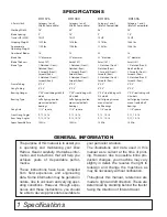
Page 4: ...Compatible Working Width 76 80 96 96 Blade Spacing 9 7 5 9 7 5 Tractor HP MAX 75 HP 75 HP 75 HP 75 HP Shipping Weight 1229 lbs 1326 lbs 1376 lbs 1466 lbs Approximate Operating Weight 1109 lbs 1206 lb...

Page 5: ...URE TO FOLLOW THESE INSTRUCTIONS COULD RESULT IN SERIOUS INJURY OR DEATH Replace Decals Immediately If Damaged Check that all safety decals are installed and in good condition Replace if decals are wo...

Page 6: ...15240 Check that all reflector decals are installed and in good condition Replace if decals are worn or dam aged DH1376 and DH1380 Reflector Decals 9 RED REFLECTORS 5TL15199 Check that all reflector d...

Page 7: ...hine An untrained operator exposes himself and bystanders to possible serious injury or death PREPARATION Always wear relatively tight and belted clothing to avoid getting caught in moving parts Wear...

Page 8: ...ep slopes Do not stop start or change directions sud denly on slopes Always operate down slopes never across the face Use extreme care and reduce ground speed on slopes and rough terrain Keep alert an...

Page 9: ...engine running Keep all persons away from operator control area while performing adjustments service or maintenance Tighten all bolts nuts and screws to torque chart specifications Check that all cott...

Page 10: ...delivering it to the customer The following check list is a reminder of points to inspect Check off each item if it is found satisfactory or after proper adjustment is made ____ Check that all safety...

Page 11: ...in locked up position at all times Never allow children or untrained persons to operate equipment Keep bystanders away from equipment NEVER GO UNDERNEATH EQUIPMENT Never place any part of the body un...

Page 12: ...le attempting to adjust will result in excessive time and labor loss due to changing conditions While making your initial run observe the disc closely as it is traveling It should be level from the fr...

Page 13: ...3 point lift discing shallow the first time over NOTE Some experimentation may be required by trial and error to arrive at proper solution A Increase speed B Increase angle on rear gangs C Decrease an...

Page 14: ...to avoid entanglement in moving parts Wear sturdy rough soled work shoes and protective equipment for eyes hair hands hearing and head Gang Assembly for Maintenance When performing maintenance or repa...

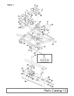
Page 15: ...Parts Catalog 12 Figure 1 Set of Lower Hitch Bushings for iMatch Sold Separately...

Page 16: ...L DH1396 2 5TL14974 FRONT GANG BEAM 4 X 3 X 41 MODEL DH1396 2 23 5TL12021 TUBULAR GANG HANGER FOR 4 X 3 BEAM 8 24 5TL11972 3 4 U BOLT FOR 4 X 3 BEAM 8 25 5TL14630 REAR GANG BEAM 4 X 3 X 33 MODEL DH137...

Page 17: ...5214 HEX BOLT 5 16 X 11 4 GR 2 2 49 5TL15208 CAT 2 TOP LINK PIN 4 3 8 USABLE LENGTH 1 50 5TL15211 CAT 2 BUSHING 2 7 8 1 51 5TL15207 CAT 1 TOP LINK PIN 43 4 USABLE LENGTH 1 M S Model Specific Parts Cat...

Page 18: ...TL9226 FLANGE LOCK NUT 1 2 MS 8 5TLT733 HEX BOLT 1 2 X 11 2 GR 2 MS 9 5TLT26 HEX NUT 1 2 MS 10 5TLT25 LOCK WASHER 1 2 MS 11 5TLT803 SCRAPER BAR CLAMP U CLAMP 1 HOLE 8 12 5TL9356 2 HOLE CLAMP MS 13 5TL...

Page 19: ...the other side fits the left front and right rear When mounting scraper arm blade assemblies ref 16 to bottom of scraper bar ref 13 use 2 hole clamp ref 12 on top of scraper bar ref 13 and fasten tog...

Page 20: ...2 12 5TL14985 FLAT WASHER 7 16 2 13 5TL9354 FLAT WASHER 5 8 1 Ref Part Description Qty Reference Figure 3 To attach balk breaker to disc remove the two top bolts from ref 1 shank bracket and slide on...

Page 21: ...equip ment on rear gangs of the DH13 series To attach outriggers remove cast iron end washer ref 8 3 4 flat washer ref 9 3 4 lock washer ref 10 and 3 4 hex nut ref 11 from 3 4 x 3 1 2 Gr 5 bolt ref 6...

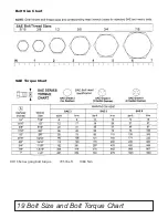
Page 22: ...19 Bolt Size and Bolt Torque Chart Bolt Size Chart SAE Torque Chart DH13 Series gang bolt torque 795 lbs ft 1080 N m...

Page 23: ...Notes 20 Notes...

Page 24: ...2014 Monroe Tufline Manufacturing Inc All Rights Reserved PART NO 5TL15193...

Reviews: