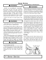
6”x6” blocks securing
gang for storage
11 Owner Service
• NEVER GO UNDERNEATH EQUIPMENT.
Never place any part of the body underneath
equipment or between moveable parts even
when the engine has been turned off. Hydraulic
system leak down, hydraulic system failures,
mechanical failures, or movement of control
levers can cause equipment to drop or rotate
unexpectedly and cause severe injury or death.
• Service work does not require going under
-
neath.
• Read Manual for service instructions or have
service performed by a qualified dealer.
The information in this section is written for oper-
ators who possess basic mechanical skills. If you
need help, your dealer has trained service techni-
cians available. For your protection, read and
follow the safety information in this manual.
• Keep all persons away from operator control
area while performing adjustments, service, or
maintenance.
• Before dismounting power unit or performing
any service or maintenance, follow these steps:
disengage power to equipment, lower the 3 point
hitch and all raised components to the ground,
operate valve levers to release any hydraulic
pressure, set parking brake, stop engine, remove
key, and unfasten seat belt.
• Always wear relatively tight and belted clothing
to avoid entanglement in moving parts. Wear
sturdy, rough-soled work shoes and protective
equipment for eyes, hair, hands, hearing, and
head.
Gang Assembly for Maintenance
•
When performing maintenance or repairs make
sure the equipment is in the lowered position
and both the mainframe and gangs are properly
blocked and secured to prevent rolling. Failure
to do so can cause serious injury or death.
When gang component replacement is required,
carefully observe all safety issues. Place unit on
level ground prior to gang drop. Also make sure
that gangs are blocked to keep them from rolling
in either direction. After unit is lowered to ground
and gangs are secure, loosen nuts on all hex
bolts holding hangers to main frame (item 10).
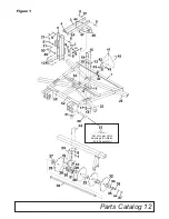
Observe the sequence and location of each
gang component and refer to the gang diagram
on Figure 1 for removal and replacement of the
desired component. After replacement is com-
pleted reinstall gang parts in proper order as
shown on gang diagram on Figure 1. Make sure
that the gang nut on the gang axle is properly
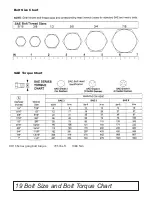
tightened after replacements are made. Refer to
" Bolt Tightening Torque Chart" on page 19 for
proper torque.
Storage
When storing your disc harrow make sure the
unit is placed on level ground and that the gangs
are properly chocked by bracing with 6”x6”
blocks on the front and rear side of one com-
plete gang assembly. See the diagram below.
WARNING
WARNING
WARNING
CAUTION
Owner Service
Summary of Contents for DH1376
Page 1: ...DH13_5TL15193_7 10 2014 DH1376 DH1380 DH1396 DISK HARROWS O P E R A T O R S M A N U A L...
Page 15: ...Parts Catalog 12 Figure 1 Set of Lower Hitch Bushings for iMatch Sold Separately...
Page 23: ...Notes 20 Notes...
Page 24: ...2014 Monroe Tufline Manufacturing Inc All Rights Reserved PART NO 5TL15193...


