7 Dealer Instructions
Pre-Assembly
Mast Weldment and Strut Assembly
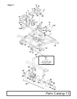
Reference Figure 1(Pg. 12).
Cut banding and remove unit from pallet. Remove
hex nut & lock washer (ref. #7 & #8) from 3/4" x
6" Gr. 5 bolt (ref. #10) and clamp plates (ref. #9)
from mast weldment (ref. #2). Take mast weld-
ment (ref. #2) off and turn it to the upright position.
Reapply clamp plates (ref. #9), lock washer &
hex nut (ref. #7 & #8) to 3/4" x 6"Gr. 5 bolt (ref.
#10), but do not tighten. Remove the 3/4" x 5" Gr.
5 bolt (ref. #6) and the 2 1/4" strut spacer (ref. #4)
in the top of the mast weldment (ref. #2). Also,
remove the 7/8" x 4" Gr. 5 bolt (ref. #5) from the
strut lug on the frame (ref. #1). Struts (ref. #3 &
#3A) are banded to the top of the frame (ref. #1).
Cut band and attach struts (ref. #3 & #3A) to
frame (ref. #1) and mast weldment (ref. #2) using
bolts (ref. #6 & #5) removed from previous step.
The assembly manual tube (ref. #47) should be
mounted to the left strut (ref. #3A) looking from
rear. Strut spacer (ref. # 4) should be placed
between the left and right strut (ref. #3 & #3A)
when reapplying the 3/4" x 5" Gr. 5 strut bolt (ref.
#6) in the mast weldment (ref. #2). Once mast
weldment (ref. #2) and struts (ref. #3 & #3A) are
in place, tighten all fasteners.
The unit is shipped with the smv safety reflector
inverted. Loosen and remove the two 5/16’”
lock nuts and bolts. Remove the reflector and
flip to correct position and re-insert the bolts
and tighten locknuts.
DH13 Lower Hitch Ear Option
The lower hitch ear holes on the DH13 series
can be used if more lift height is required.
Follow standard mast weldment and strut
assembly and use appropriate hole to meet
height needs.
Dealer Checklist
(Dealer’s Responsibility)
Inspect the equipment thoroughly after assem-
bly to be certain it is set up properly before
delivering it to the customer. The following
check list is a reminder of points to inspect.
Check off each item if it is found satisfactory or
after proper adjustment is made.
____ Check that all safety decals are installed
and in good condition. Replace if damaged.
____ Check all bolts to be sure they are tight.
____ Check that all cotter pins and safety pins
are properly installed.
____The disc gangs have been pre assembled
and mounted to the main frame at the factory.
It
is important for the dealer to visually check
and make sure all parts are in tact prior to
delivery to customer.
____ Show customer the safe, proper proce-
dures to be used when mounting, dismounting,
and storing equipment.
____ For mounted units, add wheel weights,
ballast in front tires, and/or front tractor weight
to enhance front end stability. A minimum 20%
of tractor and equipment gross weight must be
on front tractor wheels. When adding weight to
attain 20% of tractor and equipment weight on
front tractor wheels, you must not exceed the
ROPS weight certification. Weigh the tractor
and equipment. Do not estimate!
____ Show customer how to make adjustments.
____ Present Owner’s/Operator’s Manual and
request that customer and all operators read it
before operating equipment. Point out the
manual safety rules, explain their meanings
and emphasize the increased safety hazards
that exist when safety rules are not followed.
____ Point out the safety decals. Explain their
meaning and the need to keep them in place and
in good condition. Emphasize the increased
safety hazards when instructions are not fol-
lowed.
____ Explain to customer the potential crushing
hazards of going underneath raised equipment.
Instruct customer that service work does not
require going underneath unit and never to do
so.
____ Complete the Warranty Registration locat-
ed on the Frontier website.
DEALER INSTRUCTIONS
Summary of Contents for DH1376
Page 1: ...DH13_5TL15193_7 10 2014 DH1376 DH1380 DH1396 DISK HARROWS O P E R A T O R S M A N U A L...
Page 15: ...Parts Catalog 12 Figure 1 Set of Lower Hitch Bushings for iMatch Sold Separately...
Page 23: ...Notes 20 Notes...
Page 24: ...2014 Monroe Tufline Manufacturing Inc All Rights Reserved PART NO 5TL15193...


