12
MIG/MAG WELDING
Caution!
Before starting up for the first time, read the sections headed
"Safety rules" and "Starting to use the power source".
- Clamp the earth cable to the workpiece
- Plug the machine into the mains
- Shift the mains switch to the “I” position
- Set the welding voltage with step switch , and the wirefeed speed with
the wirefeed-speed dial , as per the printed scale and the “Welding
parameters” adjustment table
- Shift the operating mode selector switch into the required position
- Open the gas-cylinder valve
- Set the gas flow-rate
- Press the torch trigger and start welding
SETTING THE OPERATING POINT
One of the basic preconditions for obtaining an optimum welding result with
the MIG/MAG welding process is that the operating point has been determined
correctly. This is basically effected by selecting mutually compatible welding
voltages (step switch ) and wirefeed speeds (wirefeed-speed dial ).
In order to make it easier for the user to make the necessary settings, there
are adjustment tables printed onto the detachable side panel of the power
source. These tables contain setting-data for an unalloyed wire electrode
(SG2/SG3) with a diameter of 0.6 - 1.0 mm (VST 247), or 0.8 - 1.2 mm (VST
317 / 317-2) for welding under different shielding gases (C0
2
, mixed gas 82/
18).
N.B.!
Manufacturing tolerances and alloy tolerances of welding wires may
necessitate corrections to the welding voltage and/or wirefeed speed. This is
also true when other shielding-gas mixtures are used.
EXAMPLE OF A SETTING (VST 247)
The following values are given:
- Base metal: St 360
- Type of weld: Fillet weld h (horizontal)
- Thickness of material: 0.8 mm
- Shielding gas: Mixed gas 82/18 (M21)
- Wire diameter: 0.6 mm / SG2
This results in the following setting parameters as per the table:
- Step switch in Position 2
- Wirefeed-speed dial on 3.3 m/min (black inside scale)
- Welding current approx. 32 A
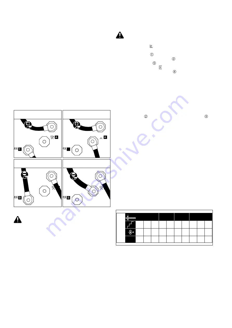
POLARITY REVERSER
The polarity reverser is for changing the polarity of the electrode; e.g. when
welding filler wires on the minus pole.
N.B.!
The polarity reverser is only fitted to VST 317 and VST 317-2 welding
machines, and is located on the inside of the power source.
CO
2
socket
- steep current rise, suitable for the dip-transfer range under CO
2
and mixed
gas
- risk of increased spattering in the medium and upper welding ranges
Ar/CO
2
MIX socket
- shallow current rise; can be used from the dip-transfer range upwards with
mixed gas, and otherwise in the intermediate and spray-arc ranges
- less spattering, thanks to softer arc
- risk of impaired ignition in the lower welding range
Caution!
When changing the polarity, always make sure that the
connections are screwed down firmly to the threaded terminal ends.
Torch: Plus pole
Workpiece: Minus pole (Inductance tap B)
*
C O
2
Torch: Plus pole
Workpiece: Minus pole (Inductance tap A)
Torch: Minus pole (Inductance tap B)
Workpiece: Plus pole
Torch: Minus pole (Inductance tap A)
Workpiece: Plus pole
Fig.16
Connection configurations for polarity reverser on VST 317 / 317-2
Factory setting
Fig.17
Excerpt from “Welding parameters” adjustment table
1
2
3
4
5
6
7
8
9
10
2.5
3.3
4.7
6.8
10.0
15.5
18.0
25
32
40
58
77
100
120
0.6 - 0.8
1.0 - 1.5
SG2
0.6 Ø
2.0
Ar
82 %
CO
2
18 %
A
mm
Summary of Contents for VST 247
Page 2: ...2...
Page 17: ...1 ENGLISH OPERATING INSTRUCTIONS...
Page 18: ...2...
Page 33: ...1 FRAN AIS MODE D EMPLOI...
Page 34: ...2...
Page 49: ...ERSATZTEILLISTE SPARE PARTS LIST LISTE DE PI CES DE RECHANGE ud_fr_st_tb_00150 012000...


