


28
Mechanical components
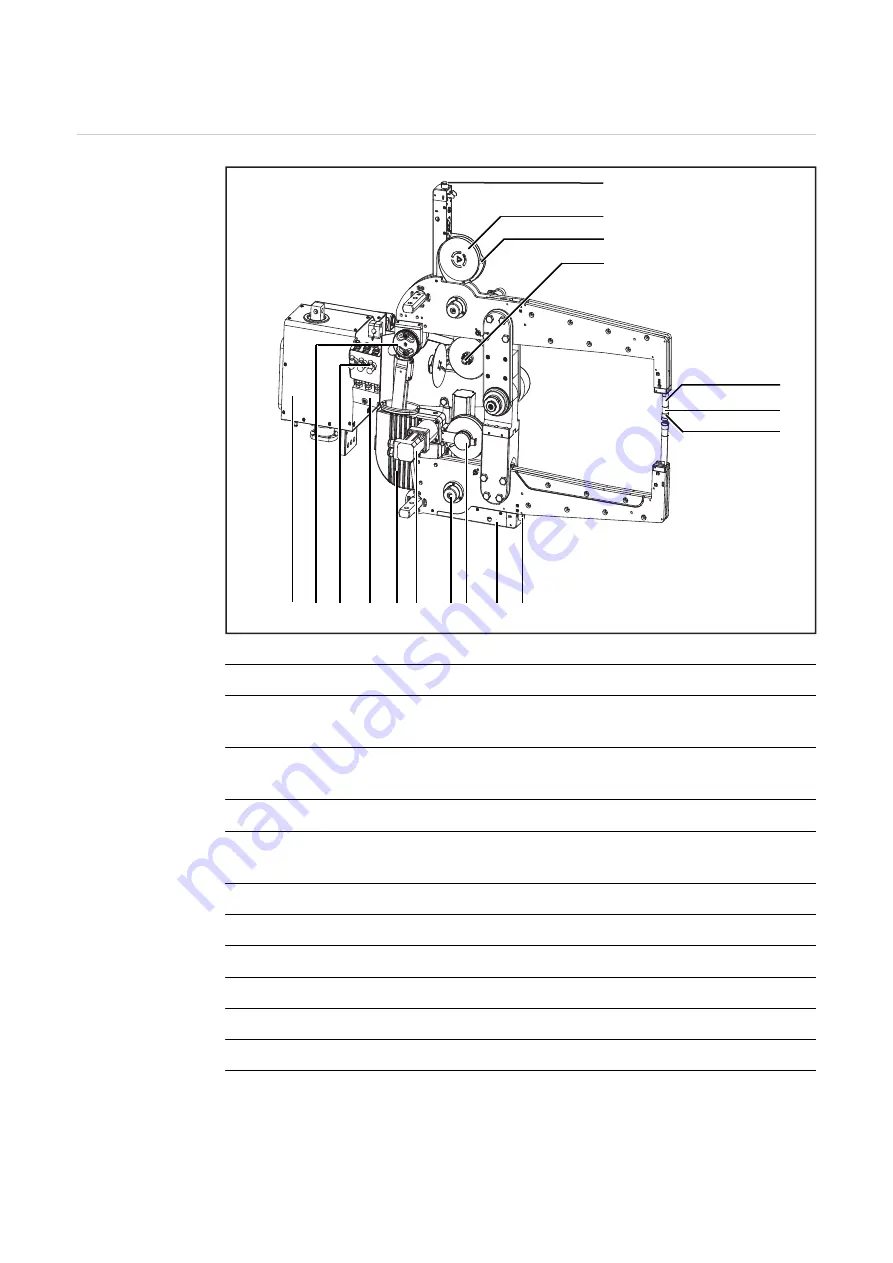
X-gun mechanical
components
Mechanical components
(1)
Lock for process tape holder
(2)
Process tape holder
to hold unused process tapes
(3)
Process tape securing device
prevents process tape from unrolling by itself
(4)
Process tape brake
(5)
Process tape spooling device with drive
to hold used process tape
(6)
Electrode shaft
(7)
Spring
(8)
Process tape guide cap with electrode
(9)
Main drive
(10)
Welding gun drive
(11)
Water distribution block
(12)
Flow watchdog
(1)
(2)
(3)
(4)
(6)
(7)
(8)
(14)(13) (12)(11) (10)(9) (4)(5)
(1)
(2)
Summary of Contents for DeltaSpot
Page 2: ...0...
Page 4: ...2...
Page 16: ...14...
Page 17: ...General information...
Page 18: ......
Page 22: ...20...
Page 23: ...Control elements and connections...
Page 24: ......
Page 36: ...34...
Page 37: ...Start up...
Page 38: ......
Page 47: ...45 EN 1 6 1 2 3 7 1 1 8 1 9 1 2 10 1 11 11...
Page 54: ...52...
Page 55: ...Spot welding...
Page 56: ......
Page 60: ...58...
Page 61: ...Troubleshooting and maintenance...
Page 62: ......
Page 71: ...69 EN 3 11 Nm 3 4 4 5 5 5 6 24 Nm 6...
Page 74: ...72 Disposal Dispose of in accordance with the applicable national and local regulations...
Page 77: ...Appendix...


