


VYPER
™
VARIABLE SPEED DRIVE
INSTALLATION
100-210 IOM (
JUL
09)
Page 24
CONTROL WIRING
NOTE: Use 18AWG (0.750 mm
2
) twisted pair, 100% shield
with drain. If the wires runs are short and contained
within a cabinet which has no sensitive circuits, the use
of shielded wire may not be necessary, but is always
recommended.
Vyper
™
packaged systems have all required sensors and
transducers factory mounted. Remote systems are field-wired
at the installation site.
Follow these requirements for control wiring:
•
Base
wire gauge requirements on 167°F (75°C).
•
Use Copper wire only; use of Aluminum wiring is not
permitted.
•
Use wire with an insulation rating of 600V or higher.
•
Separate control and signal wires from power wires
by at least 12 in. (30 cm).
Recommended Digital Signal Wire
Unshielded Per US NEC or applicable electrical code.
Shielded
18AWG (0.750 mm
2
), 3 conductor, shielded.
Table 9 – Digital Control Signal Wire Recommendations
ELECTRICAL WIRING CONDUIT
All Vyper
™
power and control wiring must be contained in
suitable metallic conduit and separated by system/compo-
nent as follows:
•
Compressor motor wiring
•
Oil pump motor wiring
•
Compressor motor cooling fan power wiring
•
Control wiring between the
Quantum
™
LX panel and
the Vyper
™
•
System Analog and Communications wiring
TRANSFORMERS
NOTE: Use only K-4 Standard rated transformers.
In most installations, the transformer that supplies the refrig-
eration equipment is the same transformer that powers most
of the other loads in the same building. These transformers
are generally very large relative to the refrigeration load.
In some cases there will be an individual transformer, sized
and dedicated to the refrigeration system alone. For example,
when a 460 VAC VSD is used and the existing power is 208V,
a 208 V to 460V step-up transformer should be installed.
Dedicated transformers must be specially sized for Vyper
™
applications. Failure to properly size the transformer may
result in unreliable operation.
NOTE: Contact the factory
or power provider for transformer sizing.
When installing a Vyper
™
on an existing transformer, the total
Kilovolt-amps (kVA) requirement of the VSD controlled system
and all branch circuits must be considered. Size the trans-
former supplying the Vyper
™
so that the transformer voltage
does not sag more than 5% when subjected to load excursions.
The steady-state operating voltage should be within the range
of 414 to 508 VAC, 3 phase 60 Hz, or 342-423 VAC, 3 phase,
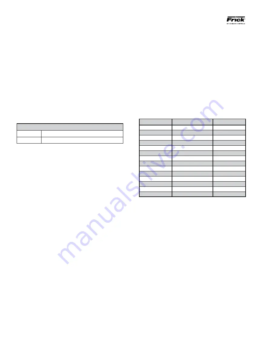
50 Hz. Refer to Table 10 for transformer ratings/sizes.
Johnson Controls offers a line of recommended Vyper
VSD Transformers. These transformers have the following
features:
•
Steel core for low flux density operation.
•
Standard K-4 rating. K-13, K-20, K-30 is available as
an option.
•
UL / CSA certified.
•
600 Volt class
•
Primary Voltage: 208V, 230V, 460V, 575V
•
Conductors, 40°C ambient
•
Sinusoidal loading not to exceed K-4
•
Secondary Voltage: 460
•
NEMA 2 housing
•
60 Hz, 150°C temperature rise, 220°C insulation
•
Taps: 1 plus, 1 minus@5%
kVA
Impedance
Weight (lb)
175
5%-6%
1100
220
5%-6%
1470
275
5%-6%
1750
330
5%-6%
1990
440
5.5% - 6.5%
2700
550
5.5% - 6.5%
3100
660
5.5% - 6.5%
3600
750
6% - 7%
4600
880
6% - 7%
5300
990
6% - 7%
5800
1250
6.5% - 7.5%
6200
1500
6.5% - 7.5%
6800
1750
6.5% - 7.5%
7500
2000
6.5% - 7.5%
8200
Table 10 – Recommended Transformer Sizes
POWER FACTOR CAPACITORS
Power factor correction capacitors are not required since the
Vyper
™
has a 0.95 minimum power factor at all operational
loads and conditions. Capacitors can be located at one or
several places on a distribution system and solid-state motor
controllers may not run or have difficulty starting units with
this scenario. The severity of the malfunction depends on the
size of the capacitors, the distance away for the solid-state
controls, and the size of the building supply transformer.
In Variable Speed Drive (VSD) applications, there is no way
to know in advance whether the capacitors will cause interfer-
ence. When a VSD is started and there are problems caused
by power factor capacitors; the capacitors require removal.
Note that in some installations, capacitors are switched on-
line as the power factor drops.
The switching transients created by connecting and discon-
necting power factor capacitors may cause the Vyper
™
to drop
off-line. High voltage power factor capacitors may be located
on the primary side of the transformer supplying power to
the Vyper
™
without causing any malfunction to equipment
located on the secondary side.


