background image

Page 108 

Trouble Shooting

Service Manual Deli Multisserie   form 9123560  rev. 02/2017

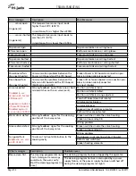
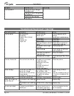
Description of part

Symptoms

Possible cause

Action

Sensor

Temperature read-out on 
LCD is not stable.

Upper sensor defect. 
Wire loose.

Check sensor and wiring. 
See also input test in service 
menu

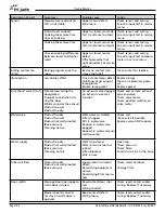
Product over cooked. 
Cooking takes more time. 
Uneven cooking.

Upper or lower sensor de-
fect. (resistance too low)

Check sensor and wiring. 
See also input test in service 
menu

Cooking takes more time

Upper or lower sensor de-
fect. (resistance too high).

Check sensor and wiring. 
See also input test in service 
menu

Uneven cooking (difference 
between lower and higher 
racks)

Upper or lower sensor 
defect. 
Offset parameter not 
right adjusted. See service 
menu.

Check sensor and wiring. 
See also input test and para-
meters in service menu.

Sliding contact (on 
rotor)

Baking program ends too 
soon

Bad or no contact (resi-
stance too high).

Clean contact or replace.

Illumination

Less display effect

One or more lamps defect 
Calcifying or greasing of 
lamp glasses 
Broken lamp gasket

Replace lamps. 
Clean or replace lamp glas-
ses. 
Replace gasket

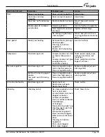
Air exhaust valve (Vent)

Steam blows along the 
doorgaskets. 
Trumpet sound when clo-
sing the door 
Whisle sound at the exhaust 
Product too wet 
Product too dry

Air exhaust valve clogged 
Air Exhaust valve mal-
function

Check and or clean exhaust 
pipe and valve 
Check valve motor 
Check position switches on 
valve motor

Watervalve

Product too dry. 
Product too wet. 
Product not well proofed. 
(Bake version). 
Cleaning not ok.

Watervalve coil defect. 
Filter clogged. 
Dirt in watervalve. 
Reducer in watervalve 
clogged. 
Reducer in watervalve not 
well mounted. 

Check coil. 
Clean valve if possible. 
Replace valve AND reducer.

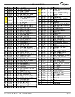
Water supply

Product too dry. 
Product not well proofed. 
(Bake version). 
Cleaning not ok.

Water tap closed. 
Water pressure too low 
(<2bar). 
Filters blocked. 
Kink in hose. 

Open tap. 
Check pressure. 
Check filters 
Search for a kink in the hose.

Tubes calcified

Product too dry. 
Product not well proofed. 
(Bake version)

Supply water not decal-
cified. 
Decalcifying equipment 
not ok. 
Decalcifying filter satura-
ted.

Check water hardness. 
 
Change filter.

Door switch

Message door open appears 
while door is closed

Reed contact door shor-
ted. 
Wiring shorted.

Check reed contact and/or 
wiring. Replace if necessary

Blowers,heaters and ro-
tor stay on while door is 
opened.

Reed contact defect. 
Wiring loose.

Check reed contact and/or 
wiring. Replace if necessary

Summary of Contents for Deli Multisserie with GC and condensor

Page 1: ...attended a training for this product you should read in its entirety the repair procedure you wish to performto determine if you have the neces sary tools instruments and skills required to perform th...

Page 2: ...Page 2 Table of Contents Service Manual Deli Multisserie form 9123560 rev 09 2017...

Page 3: ...09 11 9 2017 Rinse agent drawings page 83 and 138 adapted General technical data 6 Programming instructions 8 Display and keys 8 Setting the Multisserie 8 Add a program 9 Add a program 10 Program star...

Page 4: ...44 exchanging the 3 way drain valve 46 exchanging the emergency switch 48 exchanging the doorswitches 49 exchanging the doors and door parts 50 Exchanging soap injection parts 54 Electrical tests 56...

Page 5: ...ater and steam system 114 Blowers and heating 116 Rotor drive system 118 Drain and vent system 120 Soap injection system 122 Underframe untill ser nr 100055089 september 2011 124 Underframe from ser n...

Page 6: ...S 475 kg 1047 LBS 565kg 1246 lbs Height 74 1 4 87 7 32 74 1 4 87 7 32 Width 39 3 16 39 11 16 39 3 16 39 11 16 Depth 52 52 13 16 52 52 13 16 Voltage 208 120 V 208 120 V 208 120 V 208 120 V Phase 3 5wir...

Page 7: ...Cleaning agent Use sediment pre filter or a strainer for the reduction of silica and other non dissolved sediments plus an active carbon pre filter for the reduction of chlorine In case of water hardn...

Page 8: ...se of pro gram Switching ON Press for 3 seconds Press 6 seconds for key test Switching OFF Press both keys for 3 seconds Settings tab Combination of dial and up down left right keys Stop cancel of pro...

Page 9: ...erie form 9123560 rev 02 2017 ADD A PROGRAM Press program key Note when a pincode has been set first en ter the pincode and confirm with OK Add program by using the dial and confirm with OK Edit the p...

Page 10: ...Vent position Note that the first column the core probe temperature can be disabled in the service menu Program next cooking step if necessary Program temperature HOLD if necessary Select next time ta...

Page 11: ...reheating step is activated in mana ger menu the multisserie will start up with the preheat program after the program start After reaching the preheat temperature the display will indicate load produc...

Page 12: ...Page 12 Programming Instructions Service Manual Deli Multisserie form 9123560 rev 02 2017 PROGRAM STOP Press cancel key Select yes with the dial and confirm with OK...

Page 13: ...stop key again to resume Interrupting active program Editing a program Deleting a program Running in test program Demo mode Press program key Note when a pincode has been set first en ter the pincode...

Page 14: ...steam The water quantity is controlled by one or more soleno d valves By shortly 0 1 second opening the soleno d valve small amounts of water come through Shortly opening the soleno d valve is called...

Page 15: ...firm with OK Select yes with turning knob and confirm with OK In the test program you can run a program and you have the possibility to change time and temperature during the process Press program ke...

Page 16: ...ill si mulate the machine heating up only through software All other functions are still active Continues rinse It is also possible to have a continues rinse To achieve this the unit has to be set to...

Page 17: ...s been made more convenient Files form version V5 01 03 can be used in this version USB COMMUNICATION AND SCREEN OPTIONS How to read out the software version firmware 1 Switch ON the unit push 3 sec 2...

Page 18: ...firmware This software can be found and downloaded from the Frijado website and can also be sent by e mail as an attachment It comes in a zip file with the version number of the software for example V...

Page 19: ...names and folders The folder PROGRAMS is used for loading AND saving of recipes cookbooks This folder will be automaticly made when saving recipes The name of the file can be choosen freely for exampl...

Page 20: ...choosen freely for example parfile File extensions are related to the device type For example mts Multisserie SAVING ERROR HISTORY AND OR HACCP LOGS information service manager Insert the USB stick i...

Page 21: ...e filter replaced no no yes Clear error no yes Service 4878 device type Multi STGi Multi M Bake BSi STOi Condensor No no yes auto correct time no time set language englisch englisch deutsch francais n...

Page 22: ...in 0 10 Dry soak 10 min 0 30 Wet soak 30 min 0 60 Rinsing 4 min 0 10 Drying 30 min 0 60 Cold flush time 60 10 60 complete cleaning yes no yes PID factors P 100 0 100 I 5 0 100 D 50 0 500 iMax 100 Rela...

Page 23: ...no yes Buzzer set 0 0 4 Key beep yes no yes water capacity filter 50 30000 or for infinite Lime filter Remaining capacity of lime filter Lime filter replaced no no yes Clear error no yes Service 4878...

Page 24: ...ax 100 10 300 Relay actions 80 16 160 Energy Volts 230 1 260 Model M_Bake none Pressure no no yes I O test Read the inputs and set the outputs Ignore errors no no yes grease separator no no yes save H...

Page 25: ...265 ml 1st quantity 0 10 min blower low 8 min 4 min 2 7 min 2nd quantity is 50 of 1 3rd is 33 of 1 soaking 10 min 10 min 10 min 0 30 min Each step everything is switched off steam injecti on Adjusta...

Page 26: ...baskets 2 Remove the fat filters 278 Lift and take out Note that in case this is not possible due to car bon build up behind the filters continue at point 3 3 Remove the filter holder 275 4 capnuts M6...

Page 27: ...ust remove the seal and the adjusting ring Reverse the procedure to assemble EXCHANGING THE SHAFT SEAL 9191244s 12 14 13 15 11 Disconnect the power supply first Remove the blower blade and shaft seal...

Page 28: ...cerning chapter to assemble the blowers Keep blower motor and fan blade together 16 17 DISASSEMBLING THE SHAFT TRANSIT SPACER Remove the blowers and shaft seals accor ding prior procedure On the backs...

Page 29: ...lt centre up against the inner oven wall and mount the 4 blolts half fastened M5x10 serrated 6 Mount the 3 bolts on the inside and fasten them M5x18 7 Remove the redundant sealant with a cloth or the...

Page 30: ...le of the spacer 15 Connect the wiring to the screw terminals of the blower motor and mount a new cable tie 16 Mount the vane switch assembly 290 2x bolt M5x10 serrated 17 Mount the vertical air sucti...

Page 31: ...he ventilator blade with short left right movements Slide the ventilator blade as far as possible to the back on the shaft 21 Fasten the screw 22 Place the fan plate 277 23 Fasten the swivels of the w...

Page 32: ...the transparent safety panel 573 4 Check the presence of the numbering on the wiring of the heating elements and make a note of this Note that the numbers are laser marked on the wires see example 5 P...

Page 33: ...ff at the same time 3 Remove the lamp Push the lamp agains the spring to one side of the lamp holder and pull it down 4 Install a new halogen lamp 120 V 150 W First press one side of the lamp into one...

Page 34: ...be the best choice because lime can be like stone 4 Check if the joints 227 in the top are open 5 Try to drill out the holes with a 19 64 drill in case it is clogged with lime or place new ones Exchan...

Page 35: ...to hold the body with a 19mm wrench from the inside of the unit 12 Unscrew the nuts of the joints with a 19mm wrench and take out the joints 13 Remove the hoses in case the angled pipes 226 need to b...

Page 36: ...s supplied It is possible to open and clean the valves as described below 7 Check and or clean the inlet filter 8 Push down and turn the opposite coil 5 ccw 9 Push down the coil turn 8 ccw and pull it...

Page 37: ...he same time check if the sprayer pipe is clean inside Clean or replace if necessary Take good notice of the sprayer positions Sprayers in the column and bottom pipe These are all tapered there is no...

Page 38: ...ealant This is 1cc of resin and 8 drops of hardener for each sprayer 2 Put the sprayer pipe from the top into the sidepost 3 Apply a general amount of mixture on the outside thread of the nipple adapt...

Page 39: ...probe 7 Remove the lower sprayer 212 Slide down the pipe below the middle ring turn it out wards and slide the pipe out of the column 8 Remove the 2 selftapping screws and take out the teflon bearing...

Page 40: ...he procedure to install Adjust the tensioner in the green area Mixing up the white wires will result in a wrong rotation direction Seen fromthe top it should rotate counter clock wise 1 EXCHANGING THE...

Page 41: ...tion switch 323 The sliding ring can stay in the sliding contact 15 Remove the core sensor from the inside the position cam disc 301 with the several spacers and the chain from the shaft 16 Unscrew 3...

Page 42: ...is preferred to use threadlocker loctite 620 on the motor shaft Take care that the fluid does not penetrate between the motor bearing and shaft 5 Check the fixation of the micro switches and the dista...

Page 43: ...ual Deli Multisserie form 9123560 rev 02 2017 Note that the front cam points in the same direction as the sheet metal spring 407 Adjustment in closed position with mounting plate 408 Adjustment in ope...

Page 44: ...ing is mounted in the middle of the contacts See side view detail Note that the contacts differ in lenght On the left side the bottom contact is longer than the top one On the right side it is shorter...

Page 45: ...bad tem perature reading causing bad cooking results Each contact is a potential risk Therefore the best way is to lead the wires from the top and bottom sensor all the way to the I O board 15 Open th...

Page 46: ...6 are directly connected to the relays The number 2 wire has been cut out the cable Note that it is also possible to disconnect the cable on the motor itself In that case you can skip the steps 1 and...

Page 47: ...w they can be recognized With help of the I O test screen in the service menu it is possible to check the functions of the valve With help of a self made test rig it is possible to check the functions...

Page 48: ...Remove the curved panel 274 2 screws The contacts of the switch are out of sight Therefore the rest of the description is with help of dismounted parts 3 Push up the lever in the middle with help of a...

Page 49: ...nge side The switch is placed parallel to the magnet B Untill serial number 100051088 the reed switch has been placed at the handle side also parallel to the magnet C Untill serial number 100051252 th...

Page 50: ...e right hand at the bottom side lower the left hand a little and lift the door from the lower hinge The weight is 15kg 8 Put the outer door on a safe place Put some carton under it when placing it on...

Page 51: ...ndle mechanism There is probably some wear causing too much slack Check this by pu shing up the lower pin 1 mm is normal Adjusting the inner door Preface The inner door must grap with the magnet holde...

Page 52: ...pplied An impact driver might be useful 2 Take out the finishing plate 153 Note that the handle profile 147 on the other side is glued to the glass and will not fall 3 Unscrew 4 screws slide out both...

Page 53: ...p and bottom latch rods are fully behind the roll of the catch as shown on picture b 2 Unscrew 2 screws on the side of the handle push out the bushes 815 and take out the handle 130 3 Push out the pin...

Page 54: ...ver 472 6 Unscrew the compressor from the bracket 4 nuts 1 4 868 Reverse the procedure to assemble Reducer 7 Unscrew the plastic nut and take the redu cer from the bracket 8 Disconnect the hoses as de...

Page 55: ...ss soap injection The compressor has a limited yield This means that when an air leak occurs somewhere the pressure will drop and the needle will not lift enough In case the bottle cap is not well mou...

Page 56: ...nce and capacitance Disconnect the mains supply first The Blowers The overview shows how the coils are connected to the terminal block on the back of the blowers It also shows the connections between...

Page 57: ...w Or 0 15 Secundary coil Or Red 0 49 Insulation Prim sec 1 Black Red Prim sec 2 White Yellow Sec 1 sec 2 Orange Orange The 6 F capacitors General Even with a capacitance meter it is impossible to de t...

Page 58: ...e expected in normal situation All voltages are related to a line voltage of 208V Blowers in high speed speed 2 in cooking program On the screw terminals of the blowers 195V On the terminal block Betw...

Page 59: ...owers will start up in high speed as explained above After 10 seconds X6 opens X4 closes X5 opens followed by the power ON sequence Passive measurements resistance and capacitance Disconnect the mains...

Page 60: ...w Or 0 15 Secundary coil Or Red 0 49 Insulation Prim sec 1 Black Red Prim sec 2 White Yellow Sec 1 sec 2 Orange Orange The 6 F capacitors General Even with a capacitance meter it is impossible to de t...

Page 61: ...to a line voltage of 208V Blowers in high speed speed 2 in cooking program On the screw terminals of the blowers 195V On the terminal block Between Red 4 and Yellow 5 195V Between Red 4 and Orange 3...

Page 62: ...n channel 4 Connect the 2 capacitors 5 Disconnect both blowers Therefore disconnect wire 60 from terminal X3 6 Do the above test again and activate output X7 Not longer than 3 seconds Wait 60 seconds...

Page 63: ...ents resistance Disconnect the mains supply first The picture overview shows which measurements can be expected without disconnecting wires Disconnect wire 1 from the terminalblock TB2 1 for further m...

Page 64: ...nr 3 is on terminal 2 and wire nr 4 on terminal 3 K7 K8 TB2 Cooking position Cleaning position Cooking pos Cleaning pos Typical voltages V V 208V 0V 0V 208V 208V 0V 0V 208V V V 0V 3 7V 3 7V 0V X16 X1...

Page 65: ...ake care of the necessary safety precautions Power 208 V between wire 1 and 3 will put the valve in operation position The indication arrow will turn clockwise cw while the valve will turn ccw In this...

Page 66: ...e terminals Each element is 13 The insulation of each element has to be 1M Active measurements On the contactor coils 208V On the heater 208V on each element 16A on each element Trouble shooting Start...

Page 67: ...this junction Exchanging the 2 white wires will change the rotation direction The motor needs to turn cw clockwise seen on the top of the cam shaft The resistances can be measured in circuit Between b...

Page 68: ...am production These two valves are connected parallel and have a reducer mounted inside Working principle The motor is controlled by output X9 of the Slave I O board Two cam switches give the feed bac...

Page 69: ...nit C PT100 PT500 PT1000 50 80 31 401 55 803 10 40 84 27 421 35 842 70 30 88 22 441 10 882 20 20 92 16 460 80 921 60 10 96 09 480 45 960 90 0 100 00 500 00 1000 00 10 103 90 519 50 1039 00 20 107 79 5...

Page 70: ...uctions in the cor responding service manual which can be found on the Fri Jado website www frijado com See next page for an over view of the equipment Disconnect both key pad cables Disconnect the ri...

Page 71: ...g Also refer to the service manual I control Mtsr M bake Multisserie Deli Bake BS i Bake Star STO i Super Turbo Oven TRC Turbo Retail Combi Overview of the control board Operate tab Program tab Start...

Page 72: ...e settings tab 3 Select service 4 Enter the password 4878 5 Push OK 6 Push OK The screen opens default with the device type BSi selected 7 Select device type if necessary 8 Push OK 9 Select the right...

Page 73: ...oller Also check for the latest software version Both can be found on the Fri Jado website www frijado com in the distributer area How to read out the software version firmware 1 Switch ON the unit pu...

Page 74: ...ly 97 59 66 67 96 92 93 86 77 128 110 TB3 Contents kit 9190193 1x NTC assembly as shown 9191254 1x Terminal numbers 0260155 1850mm wire AWG18 Applied in Deli Multisserie Bakery Multisserie 97 59 66 67...

Page 75: ...m 59 60 96 66 X3 X4 X5 X6 X7 1 Wire 127 and 128 are only used in case of a condensor hood Slide the block together Place the numbers Connect the black wire to 2 TB3 1 2 3 4 5 6 7 8 110 110 1 2 3 4 5 6...

Page 76: ...9191171 2x Straight adapter 205 9191185 Plug 207 9192248 Pressure reg 2 5Bar 212 9191179 Quick dc fem black 213 9191180 Quick dc male black 214 9191166 Quick dc fem transp 215 9191167 Quick dc male t...

Page 77: ...th tape or pen if necessary 2 Cut both tubes close behind the blue connectors 3 Place a mark on both tubes 16mm 5 8 from the cutted end 4 Push the tube with the black tape into the connector with the...

Page 78: ...k on the mister Clamp the mister with the mounting nut v in the vice Unscrew the cap a while holding the body p of the mister with a 28mm wrench on the 2 flat surfaces as hown Note that the cap is spr...

Page 79: ...ll the plates of the tool touch the needle Do not put much force on it to prevent the needle from damaging in case no vice is available a big adjustable wrench could be used see picture Unscrew the ca...

Page 80: ...me ptfe tape on the o ring cap j Apply some lubricant on the needle and make an assembly of the parts d through m as shown Note that under the head of the o ring cap j sometimes an extra spacer might...

Page 81: ...olts Points of attention The welded nuts have to point to the center of the unit See top view detail In case it does not reach the bottom caused by the remainings of the rivet nuts let it fall into th...

Page 82: ...he knife 4 Connect the 2 rinse agent injection assemblies as shown in between the hoses 5 Mount the Pump assembly 6 Guide all water hoses as shown Shorten if necessary Very important is that they cann...
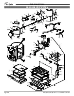
Page 83: ...ayers To Side post sprayers 7a Push the hose through the immersing weight 7b Push the stiffener sleeve into the hose 7c Pull the hose upwards untill it gets stuck M10 M11 waternozzleyellow 49 47 49 wa...

Page 84: ...air it First check if the motor is still OK Main coil 33 Between Black and Blue Start coil 45 Between Brown and Blue Both coils 78 Between Black and Brown Disconnect all wires from the motor connectio...

Page 85: ...ack wires strip and mount ringterminals Connect all wires according the overview Couper les cosse femelle du condensateur et monter anneau terminals Pincez les embouts et connecter anneau terminals eu...

Page 86: ...inted with the two ar rows 4 Turn open the control panel 5 Disconnect a The RS232 USB cable b The ribbon cable c The earth wire on the edge of the pcb d The earth wire at the bottom of the panel 6 Uns...

Page 87: ...he left side according to the procedure below It is difficult to do this for the first time because it is not possible to see the mounting nut and the lever of the adapter to release the adapter with...

Page 88: ...l becomes wider and grease and steam will leak out of the cooking chamber In these cases the grease will run be hind the curved panel on which the lower driptray is mounted Repairing this is done by d...

Page 89: ...drill as straight 90 as possible with 500 rpm maximum Use cutting grease 9 Countersink the holes till an outside diameter of 9 mm minimum and maximum 9 2 mm 45 128 23 64 See picture on previous page 1...

Page 90: ...he bottom side in case of bottom repair and place it at the top side in case it concerns the channel at the top This is because the gasket has to be pushed towards the cooking cavity Put silicon betwe...

Page 91: ...m 20x Carriage bolt M5x20 20x O ring 20x 0142315 Nut M5 2x 0141547 Nut M8 12x 2005250 Finishing plug 1x drill 3 2 mm 2x drills 5 mm 1x countersink drill 10 mm 1x can of cutting grease 8047307 1 15x 42...

Page 92: ...Carefully bend the curved panel inwards on both sides of the square hole 6 Do this with waterpumppliers in three steps as shown 7 See picture 5 7 This is necessary to get some clearance on both sides...

Page 93: ...egislations 5 Mount the new panel with the M5x45 screws with help of the nylon spacers 6 Mount the gutter with the M5x12 screws If necessary pull the drainhose on the gutter outlet with snipe nose pli...

Page 94: ...of 1x 9194890 Drilling template 1x 9191301 drill 4 0 mm 12x Self tapping pan head screw A4 4 8x13mm borstlap 55660 048 013 1x This instruction sheet Necessary tools cordless drill Normal set of tools...

Page 95: ...r pipe followed by a grey hose This hose must be hooked into the customers drainpipe The blower is separately controlled by the oven controller Software description The coldflush blower is activated 2...

Page 96: ...op of the Mul tisserie when the Internal Condenser would have been removed completely 1 Tube connection from watersprayers 2 Wire from one of the doorswitches 3 Position of the PT1000 sensor in the to...

Page 97: ...e 6 The following parts can be recognized 14 Cold flush blower 15 Connecting pipe to previous mentioned non return valve oven inlet 16 Connecting pipe on exhaust oven 17 Connecting hose silicon 18 Sli...

Page 98: ...awfoot the tool shown in picture 10 is the most convenient tool to service these couplings You need the nr 17 for the swivel and nr 19 for the moun ting nut It is possible to remove the curved back pl...

Page 99: ...marked B on the valve flange Remove the connecting pipe Unscrew the non return valve and take it out 4 Nuts marked C on picture 13 Reverse the procedure to install Exchanging the silicon gasket in th...

Page 100: ...s Weight 40kg Disconnect all tubes and wiring to and from the moving part Pull out the condenser as far as possible Picture 16 Push the lever on the guide in the direction as pointed on the guides and...

Page 101: ...al flow ventilator does not function Check the parameter cold flush in the ser vice menu It should be adjusted at 25 sec Check the software version Program the right version Version 3 91 or higher Che...

Page 102: ...version 4 30 for old CPU board Enabled in V5 00 10 of new CPU board Disabled again in s w version V6 00 10 Missing feedback signal from one or both microswitches on the air valve vent Position switch...

Page 103: ...gnals LED Positions on the boards Schematic overview Power I O board Extension board 1 All boards are connected to each other with a ribbon cable 2 The CPU board communicates by means of a serial prot...

Page 104: ...defect Core probe still hot when starting program Sliding contact on rotor dirty or defect Cooking program wrong Wrong programming Wrong product Bad cooking results uneven cooking No rotation Chain b...

Page 105: ...Less or no lighting One or more lamps defect Control defect Calcifying or greasing of lamp glasses Broken lamp gasket Bad cleaning result No steam See bad cooking due to no steam Water tap closed Filt...

Page 106: ...act s of contactor s Broken thermostat Check these items Steam leakage Controller not stable Pro grams act strange Controller switches off du ring program Visibility of LCD gets worse Leakage of steam...

Page 107: ...t Check coil resistance Check coil insulation Check bearing Check adjustment Check capacitor Check transformer Vane switch Product not ready in time Heating elements do not switch on Micro switch stay...

Page 108: ...lve Vent Steam blows along the doorgaskets Trumpet sound when clo sing the door Whisle sound at the exhaust Product too wet Product too dry Air exhaust valve clogged Air Exhaust valve mal function Che...

Page 109: ...Compressor does not give enough pressure Controller problem Check power supply capa citor coil resistance coil insulation Check membrane and lea kage of air hoses Pressure regulator Bad cleaning resu...

Page 110: ...1 20 832 25 24 832 76 45 22 867 864 17 18 13 15 14 7 865 8 9 864 10 2 74 875 74 72 864 3 73 4 1 29 28 832 10 55 56 54 52 60 61 59 6 863 67 66 65 70 71 58 57 37 871 876 874 872 873 19 75 12 11 16 21 20...

Page 111: ...ter emergency switch 40 9111200 2 Pcs Contact emergency switch 43 9191238 1 Pcs Connecting bridge 2p 44 9191237 1 Pcs Connecting bridge 3p 45 9191222 2 Pcs End clamp din rail 46 9191233 1 Pcs Rail ter...

Page 112: ...5 823 174 108 110 110 112 820 181 106 821 822 187 163 162 103 187 166 167 825 824 863 182 829 102 110 109 117 821 822 101 831 830 177 176 827 175 144 143 186 828 147 146 145 820 186 183 167 166 184 82...

Page 113: ...190461 3 Pcs Door handle top 147 9194404 3 Pcs Profile door handle 148 9193051 3 Pcs Latch rod top 149 9194269 6 Pcs Drive plate latch rod 150 9193052 3 Pcs Latch rod bottom 153 9194406 3 Pcs Finishin...

Page 114: ...l Deli Multisserie form 9123560 rev 09 2017 201 200 206 201 55 205 206 200 56 202 203 827 206 233 204 207 209 210 215 832 211 230 229 231 827 216 215 227 228 226 212 223 224 225 213 217 218 219 222 20...

Page 115: ...8 9193069 1 Pcs Seal ring teflon 219 9192084 1 Pcs Joint 220 9190429 1 Pcs Drain riddle 221 9191118 1 Pcs Female adapter straight 1 4 x1 4 222 9191117 1 Pcs Hose pillar long 1 4 223 9191091 1 Pcs Nipp...

Page 116: ...17 252 824 253 254 255 832 832 812 834 258 257 835 836 831 833 49 824 252 253 832 277 276 275 835 837 278 832 286 54 290 816 812 832 804 51 268 804 50 839 840 267 832 805 832 832 52 266 274 804 53 251...

Page 117: ...258 9194168 2 Pcs Pressure plate heater 266 9194469 1 Pcs Bracket transformer 267 9194035 2 Pcs Construction profile 268 9194023 1 Pcs Air suction channel blowers 274 9194026 1 Pcs Cover plate curved...

Page 118: ...ervice Manual Deli Multisserie form 9123560 rev 09 2017 845 314 326 848 847 857 846 48 849 832 323 854 324 60 300 803 800 301 300 832 307 302 303 304 308 832 850 851 852 318 317 30 832 61 316 329 325...

Page 119: ...in 3 8 x 7 32 316 9192015 1 Pcs Link for Chain 317 9190400 1 Pcs Rotor column 318 9192092 1 Pcs Teflon bearing 323 9194502 1 Pcs Bracket position switch 324 9194445 1 Pcs Bracket sliding contact 325 9...

Page 120: ...860 855 832 406 401 859 403 411 134 862 407 408 832 856 412 857 857 413 417 869 862 134 417 869 350 351 352 353 361 816 817 359 818 34 355 360 838 817 363 364 365 366 368 370 371 903 372 373 819 376 3...

Page 121: ...container 375 9191149 1 Pcs Grease container 376 9194840 1 Pcs Support grease container 378 9194169 1 Pcs Shim conductor greasecontainer 380 9194920 2 Pcs Support grease container support 383 9198117...

Page 122: ...nd Parts lists Service Manual Deli Multisserie form 9123560 rev 09 2017 466 457 458 459 450 467 460 461 462 463 460 465 464 466 36 472 468 35 469 868 471 453 456 451 455 454 452 450 3x452 453 454 455...

Page 123: ...cap 462 9192341 1 Pcs Plug soap bottle cap 463 9192344 1 Pcs Seal ring silicon 464 9191283 1 Pcs O ring silicon 465 9191171 1 Pcs Straight adaptor 1 8 x 1 8 clamp 466 9191157 8 Mtr Hose ptfe 6 0mm 46...

Page 124: ...3 811 511 514 808 809 510 809 805 812 515 812 517 802 525 526 521 522 523 528 518 516 155 815 517 519 800 808 800 520 811 814 524 814 803 801 800 529 506 505 507 527 805 805 511 805 507 807 506 508 80...

Page 125: ...holder 516 9194446 2 Pcs Doorstop bracket 517 9191106 4 Pcs Hinge 518 9191182 1 Pcs Magnet 36x15x11 519 9194331 1 Pcs Door underframe 520 9191107 1 Pcs Doorlock 521 9174230 1 Pcs Thethering bracket 5...

Page 126: ...814 503 509 805 512 513 863 811 511 514 808 809 510 809 805 812 515 812 517 802 525 526 528 518 516 155 815 517 519 800 808 800 520 811 529 507 527 805 805 511 805 507 807 508 800 803 804 503 806 504...

Page 127: ...253 1 Pcs Bottomplate rear 527 9194252 1 Pcs Bottomplate front 528 9070840 1 Pcs Grommet 15mm 529 9194468 2 Pcs Construction profile 530 9190563 4 Pcs Side cover curved 531 9190564 2 Pcs Front cover c...

Page 128: ...814 509 805 512 513 863 811 511 514 808 809 510 809 805 812 515 812 517 802 525 528 518 516 155 815 517 519 800 808 800 520 811 507 805 511 805 507 508 800 504 538 351 529 817 838 800 801 802 808 928...

Page 129: ...94572 1 Pcs Bracket 540 9194573 1 Pcs Bracket 541 9194574 1 Pcs Beam for controls on right side 541 9194578 1 Pcs Beam for controls on left side 542 9194564 1 Pcs Finishing plate front side 543 919456...

Page 130: ...m 9123560 rev 09 2017 805 554 878 553 832 551 552 805 551 553 832 266 267 561 834 824 559 556 832 805 555 557 832 812 558 832 812 571 879 567 807 567 569 567 562 566 563 877 877 812 832 574 574 573 27...

Page 131: ...shaped construction panel 562 9194096 2 Pcs Support profile blower not in dra wing 563 9194085 1 Pcs Cover plate right side 564 9194545 1 Pcs Leak guard 565 9194481 1 Pcs Bracket 125V socket 566 9194...

Page 132: ...123560 rev 09 2017 UNDERFRAME 2017 532 533 534 535 929 930 928 598 603 609 605 607 536 600 601 606 608 604 610 2x 602 234 960 961 832 832 585 586 611 612 614 615 616 528 613 617 618 619 961 812 896 96...

Page 133: ...tor 100 H 125 536 3701078 2 Pcs Castor with brake 100 H 125 585 9190176s Adj Castor ass 586 9190177s Adj Castor with brake ass 598 9194934 1 Pcs Holder Soap bottle 599 9194935 1 Pcs Holder Rinse agent...

Page 134: ...ts lists Service Manual Deli Multisserie form 9123560 rev 09 2017 675 667 362 669 666 665 665 664 672 672 673 673 679 660 661 662 959 837 663 674 676 678 677 670 671 805 803 832 954 only in first unit...

Page 135: ...s Elbow flexible D50 incl 2 clamps 671 7100027 1 Pcs Running trap D54 Siphon 672 9194919 2 Pcs Support between stand 673 9194921 2 Pcs Locking bracket 674 7100034 1 Pcs Endcap D40 incl 1 clamp 675 919...

Page 136: ...4 695 691 681 680 697 683 698 693 690 689 692 687 686 685 684 741 683 707 702 713 712 733 732 741 731 710 711 715 716 701 699 706 734 735 736 719 737 682 717 716 708 729 720 730 738 727 739 726 725 72...

Page 137: ...lator 720 9194736 1 Pcs Top plate back side 721 9194738 1 Pcs Construction profile 722 9194739 1 Pcs Construction profile L for covers 723 9194744 1 Pcs Cover L 724 9194741 1 Pcs Construction profile...

Page 138: ...views and Parts lists Service Manual Deli Multisserie form 9123560 rev 09 2017 RINSE KIT 779 780 777 778 776 779 777 778 777 201 770 771 770 201 772 773 774 775 201 770 771 770 201 772 773 774 775 83...

Page 139: ...ded 1 4 775 9301112 2 Pcs Plastic nipple push on 6 4mm 776 9301117 1 Pcs Tee connector D6 4 777 9301119 2 Mtr Hose PVC 6x4 mm clear 778 9301120 4 Pcs Hose clamp 6 8mm SST 779 9301072 2 Pcs Peristaltic...

Page 140: ...Page 140 Exploded views and Parts lists Service Manual Deli Multisserie form 9123560 rev 09 2017 BAKE 784 783 796 795 936 959 785 786 787 788 958 318 781 782 797 793 792 789 790 791 794 837 12x...

Page 141: ...s Guide profile baketray 792 9194057 4 Pcs Stud trayrack 793 9192232 2 Pcs Connection baking rack 794 9192210 2 Pcs Connection D14 baking rack 795 9194859 1 Pcs Cover plate bake 796 9194548 1 Pcs Cove...

Page 142: ...s Studding M6 x 180 841 0147017 4 1 Pcs Screw M2 5x16 SS Slotted pan head 842 0142293 4 Pcs Nut M2 5 SS hexagonal Pos Part nr Qty Unit Description 843 9191130 4 Pcs starlock washer 3mm black 844 01887...

Page 143: ...octite 648 50ml 9191234 Pcs Sealant 2 component 3500306 Ct Sealant silicon red 343 C 650 F 4302335 Ct Sealant silicon aluminum 230 C 450 F 4302375 Ct Sealant silicon black 200 C 400 F 9061045 Al Silic...

Page 144: ...Ringterminal M5 Red 2005763 Pcs Ringterminal M5 Blue 2006133 Pcs Receptacle female Blue 2006183 Pcs Receptacle female Red full insulated 2006222 Pcs Receptacle female Red piggyback 4310570 Rl Recepta...

Page 145: ...Page 145 Exploded views and Parts lists Service Manual Deli Multisserie form 9123560 rev 09 2017...

Page 146: ...94 3 X 208 V 4 2 1 3 6 5 7 4T2 3L2 11 11 12 12 1 1P 1L1 1L1 1L1 1L1 3L2 3L2 3L2 3L2 5L3 5L3 5L3 5L3 7L4 8T4 2T1 2T1 2T1 2T1 4T2 4T2 4T2 4T2 6T3 6T3 6T3 6T3 F5 F6 1 2 3 4 5 5 115 for product 31 0 76 5...

Page 147: ...hes airflow Soleno d valves for steam production puls controlled transformer fan speed upper fan fan lower Air air valve Water inlet choise Soleno d valves rinse water center side post compressor X7 2...

Page 148: ...a 19 E2b E2c E2c E2b 20 21 33 32 lower element E2a 31 28 E1c E1a E1b 30 29 upper element E1b E1c E1a 22 24 23 1 2 71 1 2 3 3 4 5 6 4 5 99 6 K1 K2 71 72 73 S1 74 115 115 FUSE 15 AMP FUSE 15 AMP FUSE 10...

Page 149: ...9 87 transformer 77 78 78 88 86 88 94 94 93 1 2 4 3 6 5 TB 3 filter white Door post Central Pole GEBRUIK BIJ DE 2 SCHAKELAARS ALLEEN DE BOVENSTE EN ONDERSTE CONTACTEN USE ONLY THE UPPER AND LOWER CONT...

Page 150: ...S1 74 76 K1 73 75 73 71 76 75 Filtered water Tap water 84 91 K5 12 14 11 83 3 2 1 5 6 4 7 8 9 12 37 15 amp 13 14 15 16 17 18 10 25 100 27 35 26 99 7 100 102 11 11 12 12 1 1P 1L1 1L1 1L1 1L1 3L2 3L2 3...

Page 151: ...K5 Y3 Y4 K4 C1 C2 C3 41 42 102 100 45 46 58 88 86 67 68 40 55 44 56 49 60 61 38 39 69 81 51 52 79 50 48 36 80 82 70 Rotor Light 3x150W heaters upper lower vane switches water pulsating transformer fa...

Page 152: ...1 white 40 27 26 25 35 102 85 46 7 8 9 12 11 10 30 31 29 13 14 15 18 17 16 32 28 33 1 3 4 green ABB 40amp ABB 40amp TB 4 2 3 4 7 6 5 97 TB 2 connectionblok 1 36 48 50 36 1 2 3 8 83 F5 F6 F1 F2 F3 F4 1...

Page 153: ...VALVE x4 VALVE print 2 GND x16 x17 x18 GND AIRVALVE E x19 AIRVALVE x20 103 105 104 106 x12 SPARE x13 x14 10Vin GND x15 GND 50 48 112 114 116 ground 37 40 39 38 N x15 L x14 FUSE 42 41 45 55 print 1 sp...

Page 154: ...Fri Jado Inc 1401 Davey Road Suite 100 Woodridge IL 60517 USA fax 1 630 689 1424 us info frijado com www frijado com USA toll free 877 FRI JADO For technical support call 1 877 374 5236...

Reviews: