9
100
5
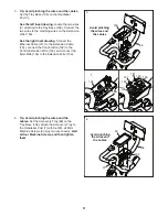
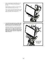
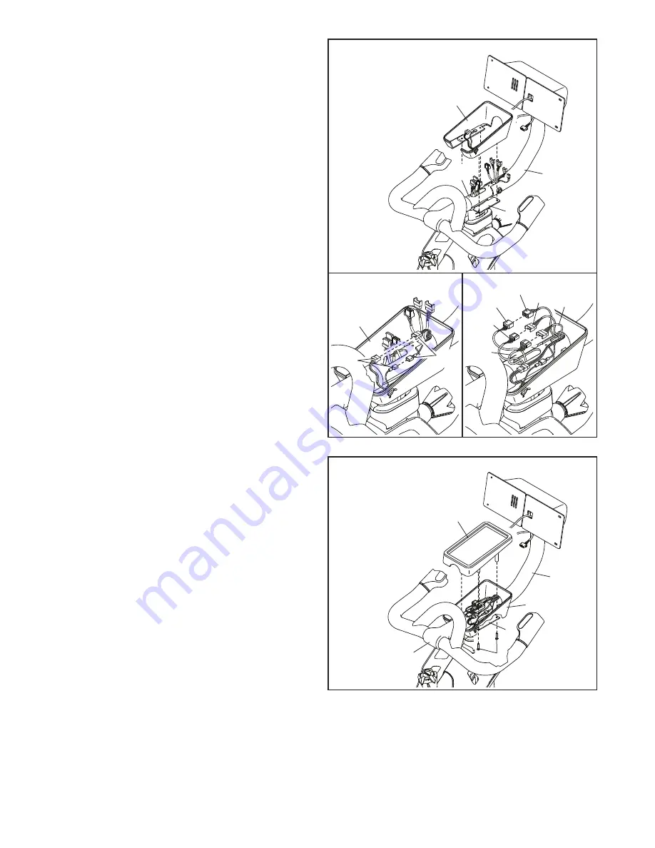
5. Tip: Avoid pinching the wires and the cables.
Set the Tray Base (100) on the Handlebar
Post (7).
See the left inset drawing. Locate the two wires
(C) attached to the Tray Base (100). Connect the
two wires to the matching wires on the Extension
Wire (150).
See the right inset drawing. Connect the
Ethernet Cable (147) to the Extension Cable
(151), connect the Control Wire (152) to the
Control Extension Wire (153), and connect the
Main Wire (146) to the Extension Wire (150).
100
147
151
153
152
150
150
Avoid pinching
the wires and
the cables
66
97
7
146
6
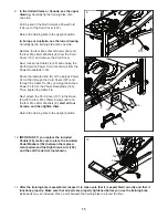
6. Tip: Avoid pinching the wires and the
cables. Set the Accessory Tray (99) on the
Tray Base (100). Attach the Accessory Tray to
the Handlebar Post (7) with four M4 x 20mm
Machine Screws (9) (only two are shown); start
all four Machine Screws, and then tighten
them.
Avoid pinching
the wires and
the cables
99
100
7
9
66
97
C
Summary of Contents for CoachBike b22.7
Page 31: ...31 NOTES ...


