background image

26

HOW TO CHANGE USER SETTINGS

IMPORTANT: Some of the settings and features 

described may not be enabled. Occasionally, a firm-

ware update may cause the console to function slightly 

differently. 

1.   Select the settings main menu.

   First, turn on the power (see HOW TO TURN ON 

THE POWER on page 18). Note: It may take a 

few moments for the console to be ready for use.

   When you turn on the console, the welcome menu 

will appear on the screen after the console boots 

up. Touch Work Out or touch My Account and log 

in to your iFit account. The main menu will then 

appear on the screen.

   If you are in a workout, touch the screen and follow 

the prompts to end the workout and return to the 

main menu. If you are in the settings menus, touch 

the back button (arrow symbol) and then touch the 

close button (x symbol) to return to the main menu.

   Then, touch the menu button (three horizontal lines 

symbol) on the screen, and then touch Settings

The settings menu will appear on the screen. 

2.   Navigate the settings menus and change 

settings as desired.

   Slide or flick the screen to scroll upward or down-

ward if necessary. To view a settings menu, simply 

touch the menu name. To exit a menu, touch the 

back button (arrow symbol). You may be able to 

view and change settings in the following settings 

menus:


 Account

    •   My Profile


  •   In  Workout

 Equipment


  •   Equipment  Info


 About


  •   Legal

   Note: Some settings will only be available if you are 

logged into your iFit account.

3.   Customize workout settings and the unit of 

measurement.

   To customize workout settings, touch In Workout

and then touch the desired settings. 

   To customize the unit of measurement, touch 

Equipment Info, and then touch the desired setting. 

The console can display speed and distance in 

either standard or metric units of measurement.

4.   View machine information.


 Touch  Equipment Info, and then touch Machine 

Info or App Info to view information about your 

trainer or about the console app.

5.   Exit the settings main menu.

   If you are in a settings menu, touch the back 

button. Then, touch the close button (x symbol) to 

exit the settings main menu. 

HOW TO CHANGE CLUB OWNER SETTINGS

1.   Select the settings main menu.

   First, turn on the power (see HOW TO TURN ON 

THE POWER on page 18). Note: It may take a 

few moments for the console to be ready for use.

   When you turn on the console, the welcome menu 

will appear on the screen after the console boots 

up. Touch Work Out or touch My Account and log 

in to your iFit account. The main menu will then 

appear on the screen.

   If you are in a workout, touch the screen and follow 

the prompts to end the workout and return to the 

main menu. If you are in the settings menus, touch 

the back button (arrow symbol) and then touch the 

close button (x symbol) to return to the main menu.

   Then, touch the menu button (three horizontal lines 

symbol) on the screen, and then touch Settings

The settings menu will appear on the screen. 

Summary of Contents for CoachBike b22.7

Page 1: ...ace above for reference QUESTIONS If you have questions or if parts are damaged or missing please see HOW TO CONTACT CUSTOMER CARE on the back cover of this manual freemotionfitness com CAUTION Read all precautions and instructions in this manual before using this equipment Keep this manual for future reference ...

Page 2: ...ademark of Garmin Ltd or its subsidiaries Google Maps is a trademark of Google Inc Polar is a registered trademark of Polar Electro Oy Wi Fi is a registered trademark of Wi Fi Alliance WPA and WPA2 are trademarks of Wi Fi Alliance This drawing shows the location s of the warning decal s If a decal is missing or illegible see the back cover of this manual and request a free replacement decal Apply ...

Page 3: ...ime the training bike is used Replace any worn parts immediately 8 Keep children under age 16 and pets away from the training bike at all times 9 When connecting the power cord see page 12 plug the power cord into a grounded circuit 10 Do not modify the power cord or use an adapter to connect the power cord to an improper receptacle Keep the power cord away from heated surfaces Do not use an exten...

Page 4: ...y press the brake knob downward 19 Over exercising may result in serious injury or death If you feel faint if you become short of breath or if you experience pain while exercising stop immediately and cool down SAVE THESE INSTRUCTIONS ...

Page 5: ...ns after reading this manual please see the back cover of this manual To help us assist you note the product model number and serial number before contacting us The model number and the location of the serial number decal are shown on the front cover of this manual Before reading further please familiarize yourself with the parts that are labeled in the drawing below Carriage Knob Brake Knob Post ...

Page 6: ...m the PART LIST near the end of this manual The number following the key number is the quantity needed for assembly Note If a part is not in the hardware kit check to see whether it has been preassembled Extra parts may be included M10 Jam Nut 125 4 M10 x 30mm Screw 121 2 M4 x 20mm Machine Screw 9 8 M10 x 55mm Bolt 102 1 M10 x 60mm Bolt 115 4 M10 Locknut 116 1 M10 Washer 112 4 ...

Page 7: ... piece of packing material under the rear of the Base 2 Have a second person hold the Frame 1 to prevent it from tipping while you complete this step Attach the Rear Stabilizer 4 to the Base 2 with two M10 x 60mm Bolts 115 two M10 Washers 112 and two M10 Jam Nuts 125 Then remove the packing material 2 2 Set a sturdy piece of packing material under the front of the Base 2 Have a second person hold ...

Page 8: ...ort slot B in the Handlebar Attach the Console Arm 66 with an M10 x 55mm Bolt 102 and an M10 Locknut 116 Make sure that the Locknut is in the hexagonal hole C firmly tighten the Bolt 3 While a second person holds the Handlebar 97 near the Handlebar Post 7 route the Main Wire 146 and the Ethernet Cable 147 upward through the long slot A in the Handlebar Tip Avoid pinching the wire and the cable Att...

Page 9: ...ion Cable 151 connect the Control Wire 152 to the Control Extension Wire 153 and connect the Main Wire 146 to the Extension Wire 150 100 147 151 153 152 150 150 Avoid pinching the wires and the cables 66 97 7 146 6 6 Tip Avoid pinching the wires and the cables Set the Accessory Tray 99 on the Tray Base 100 Attach the Accessory Tray to the Handlebar Post 7 with four M4 x 20mm Machine Screws 9 only ...

Page 10: ... on the back of the Console 10 10 151 95 94 153 150 8 8 Tip Avoid pinching the wires and the cable If necessary tilt the Left and Right Console Brackets 94 95 to make this step easier Attach the Console 10 to the Left and Right Console Brackets 94 95 with four M4 x 20mm Machine Screws 9 After you start all four Machine Screws make sure that the Console is level from side to side Then tighten the M...

Page 11: ...s 83 and the four M4 x 8mm Washers 8 from the Cord Cover 107 and remove the Cord Cover Next loosen the Cable Tie 55 and unplug the North America Power Cord not shown from the Power Receptacle 143 Route the indicated end D of the Europe Power Cord 159 through the Cord Cover 107 and through the Cable Tie 55 and plug the Europe Power Cord into the Power Receptacle 143 Then tighten the Cable Tie Next ...

Page 12: ...cover is grounded before using an adapter The temporary adapter should be used only until a properly grounded outlet can be installed by a qualified electrician WARRANTY INFORMATION The warranty for this product does not cover damage or equipment failure caused by electric wiring not in compliance with electrical codes or the specifications in this manual or failure to provide reasonable and neces...

Page 13: ...mpliance with electrical codes or the specifications in this manual or failure to provide reasonable and necessary maintenance as outlined in this manual Any failure or damage caused by unauthorized service misuse accident negligence improper assembly or installation debris resulting from any destruction activi ties in the product s environment rust or corrosion as a result of the product s locati...

Page 14: ...the top and bottom of your pedal stroke Flywheel The flywheel on the training bike has the correct inertia to allow you to pedal smoothly while encouraging you to use good pedaling form HOW TO ADJUST THE GEOMETRY OF THE TRAINING BIKE The training bike can be adjusted to match the geom etry of your road bike to promote correct form and to ensure proper training of the muscles Make adjust ments in s...

Page 15: ...e the handlebar post upward or down ward to the desired position and firmly tighten the post knob IMPORTANT Do not adjust the handlebar post beyond the stop mark on the handlebar post HOW TO LEVEL THE TRAINING BIKE If the training bike rocks slightly on your floor during use turn one or both of the leveling feet O beneath the rear or front stabilizer until the rocking motion is eliminated HOW TO U...

Page 16: ...f the training bike regularly Replace any worn parts immediately To clean the training bike use a damp cloth and a small amount of mild detergent For maximum performance and safety replace the pedals every year To purchase pedals see the back cover of this manual IMPORTANT To avoid damage to the training bike and to prevent injury to the user use only manu facturer supplied pedals Other pedals may...

Page 17: ...sistance of the pedals and the incline of the frame as it guides users through an effective exercise session With the manual mode of the console selected users can change the resistance of the pedals and the incline of the frame with the touch of a button During exercise the console will display continuous exercise feedback Users can even measure their heart rates using a compatible heart rate mon...

Page 18: ...GE CLUB OWNER SETTINGS on page 26 and manually calibrate the incline system HOW TO USE THE TOUCH SCREEN The console features a tablet with a full color touch screen The following information will help you use the touch screen The console functions similarly to other tablets You can slide or flick your finger against the screen to move certain images on the screen such as the displays in a workout ...

Page 19: ...with your finger until the club owner settings menu appears on the screen Next touch Maintenance and then touch Update The console will check for firmware updates For more information see HOW TO CHANGE CLUB OWNER SETTINGS on page 26 4 Calibrate the incline system First touch the menu button three horizontal lines symbol touch Settings and then draw a blocky figure 8 repeatedly on the screen with y...

Page 20: ...ebar You can also change the incline of the frame by pressing the Incline Decline increase and decrease buttons on the left handlebar Note After you press a button it will take a moment for the pedals to reach the selected resistance level or for the frame to reach the selected incline level Note When the training bike is declined or extremely inclined the range of resistance levels may decrease 5...

Page 21: ...se and decrease buttons repeatedly to select a fan speed or to turn off the fan Note If the pedals are not moved for a while when the main menu is selected the fan will turn off automatically 8 When you are finished exercising unplug the power cord When you are finished exercising press the power switch to the off position and unplug the power cord IMPORTANT If you do not do this the electrical co...

Page 22: ...ll upward or downward if necessary Note To use a featured workout the console must be connected to a network see HOW TO CONNECT TO A NETWORK on page 28 If you are logged into your iFit account you can save a featured workout for future use by touching the favorites button heart symbol To draw your own map for a workout see HOW TO CREATE A DRAW YOUR OWN MAP WORKOUT on page 24 When you select a work...

Page 23: ... resistance level or incline level of the frame during the workout the number of calories you burn will be affected To pause the workout simply touch the screen or stop pedaling To continue the workout simply resume pedaling To end the workout touch the screen to pause the workout and then follow the prompts on the screen to end the workout and return to the main menu When the workout ends a worko...

Page 24: ...t the bottom of the screen 4 Draw your map Navigate to the area on the map where you want to draw your workout by typing in the search box or by sliding your fingers on the screen Touch the screen to add the start point for your workout Then touch the screen to add the end point for your workout If you want to start and end your workout at the same point touch Close Loop or Out Back in the map opt...

Page 25: ...outs to your schedule on iFit com On your computer smartphone tablet or other device open an internet browser go to iFit com and log in to your iFit account Next navigate to Menu Library on the website Browse the workout programs in the library and join the desired workouts Then navigate to Menu Schedule to view your schedule All of the workouts that you have joined will appear on your schedule yo...

Page 26: ...bout Legal Note Some settings will only be available if you are logged into your iFit account 3 Customize workout settings and the unit of measurement To customize workout settings touch In Workout and then touch the desired settings To customize the unit of measurement touch Equipment Info and then touch the desired setting The console can display speed and distance in either standard or metric u...

Page 27: ... will begin automatically IMPORTANT To avoid damaging the training bike do not turn off the power while the firm ware is being updated The screen will show the progress of the update When the update is complete the training bike will turn off and then turn back on If it does not press the power switch into the off position wait for sev eral seconds and then press the power switch into the reset po...

Page 28: ...on or a wireless connection To make a wired connection plug an ethernet cable into the ethernet receptacle located on the underside of the training bike To make a wireless connection make sure that Wi Fi is enabled on the console If it is not enabled touch the Wi Fi toggle to enable it The screen will show a list of available networks Note It may take a few moments for the list of networks to appe...

Page 29: ...orkout see page 25 Then touch Connect Bluetooth Headphones when this option appears on the screen To pair your headphones to the console select your headphones from the list on the screen When your headphones and the console pair successfully the audio from the console will play through your headphones HOW TO USE THE CHARGING PORT The console features a charging port that you can use to charge USB...

Page 30: ...hielded interface cables when connect ing to computer or peripheral devices Changes or modifications not expressly approved by the party responsible for compliance could void the user s authority to operate this equipment IMPORTANT To satisfy exposure compliance requirements the antenna and transmitter in the console must be at least 8 in 20 cm from all persons and must not be near or connected to...

Page 31: ...31 NOTES ...
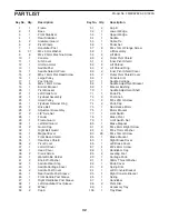
Page 32: ... Cover 45 1 Rear Saddle Post Sleeve 46 1 Front Saddle Post Sleeve 47 1 Right Handlebar Post Sleeve 48 1 Left Handlebar Post Sleeve 49 2 Wheel 50 2 Cap A 51 2 Cap B 52 1 Lower Wedge 53 1 Upper Wedge 54 1 Saddle 55 1 Cable Tie 56 1 Pedal Set 57 6 M4 x 12mm Flange Screw 58 1 Lift Assembly 59 2 Lift Boot 60 2 Outer Pivot Shield 61 2 Inner Pivot Shield 62 2 Lift Shroud 63 2 Lift Shroud Ring 64 2 Inner ...

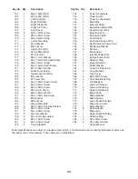
Page 33: ...andoff 143 1 Power Receptacle 144 1 Power Switch 145 1 Power Control Board 146 1 Main Wire 147 1 Ethernet Cable 148 1 Resistance Motor Wire 149 1 Speed Sensor Wire 150 1 Extension Wire 151 1 Extension Cable 152 1 Control Wire 153 1 Control Extension Wire 154 1 North America Power Cord 155 4 M8 Spring Washer 156 2 M4 Nut 157 1 M5 Locknut 158 1 Internal Power Wire 159 1 Europe Power Cord 160 1 Retai...

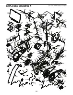
Page 34: ... 68 129 129 92 120 90 91 69 130 48 47 22 23 26 27 26 27 72 41 40 28 83 137 117 78 57 57 76 75 81 79 77 136 124 117 87 86 85 87 80 74 73 72 41 71 140 82 138 142 84 24 147 146 152 151 149 150 153 10 96 9 57 121 9 130 113 94 7 95 148 98 98 17 101 166 166 166 166 108 133 93 93 16 161 67 53 52 54 66 116 12 103 104 97 102 88 11 29 74 73 178 178 178 178 178 172 173 180 181 182 182 124 8 8 183 174 175 177...

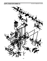
Page 35: ... 8 60 61 63 65 62 64 83 83 83 83 83 83 83 89 139 139 110 112 139 163 112 134 132 132 133 125 125 114 141 141 145 164 144 131 107 135 159 143 131 160 115 156 155 155 119 115 109 109 111 111 59 168 65 60 171 171 114 167 61 167 64 126 38 37 126 118 118 106 170 170 170 169 170 63 62 8 8 117 154 89 4 8 55 8 8 158 110 ...

Page 36: ... to retain your original invoice and serial number information If this product experiences a fail ure under the warranty terms set forth Freemotion Fitness shall provide at their option either repair replacement or refund of the purchase price Freemotion Fitness compen sates service providers for warranty trips within their service area You may be charged additionally for service calls beyond this...

Reviews: