background image


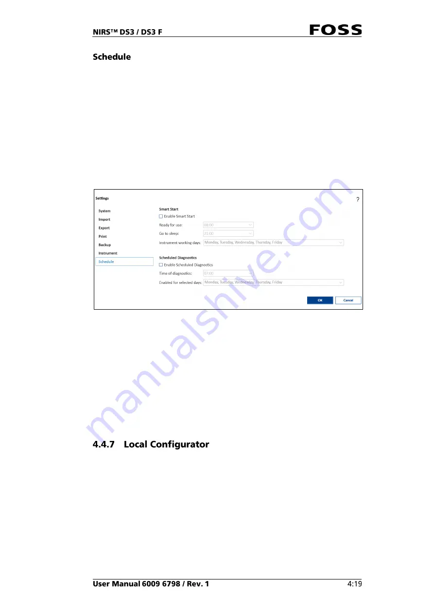
In the Schedule tab is it possible to configure: 


Smart Start  


Scheduled Diagnostic  

Smart Start helps you to save energy and wear on the instrument. 

It will automatically start the instrument and perform the instrument diagnostics so 
it is ready for use at the preferred time. It will also close down automatically.  

The computer and instrument must still be on for this to work. 

The Scheduled Diagnostics feature allows you to plan a diagnostics test to take 
place automatically at a specific time of day. 


Fig. 64


Enable Schedule Diagnostics:

 When the feature is enabled, a diagnostics test will 

be performed at the configured time. 

Time of diagnostics:

 Configure a suitable time for the diagnostics test. This could 

be in the morning before the workday begins or in a planned break during the day. 
If the Nova software is in progress with a measurement or if a dialogue is displayed 
on the screen at the time of diagnostics, the diagnostics test will wait until the 
current activity is completed. 

Enabled for selected weekdays:

 Select the weekdays on which you want the 

diagnostics test to be performed. FOSS recommends that you schedule a 
diagnostics test for every day the instrument is in use. 


The Local Configurator is an external program that is used for configuring the local 
setup. A similar setup can also be done using the FossManager setup (network 
setup). 

The Local Configurator is described in the Installation Manual.  

Summary of Contents for NIRS DS3

Page 1: ......

Page 2: ...nformation contained in this manual is subject to change without prior notice For the latest information about documentation updates for your specific instrument please contact your local FOSS representative ...

Page 3: ......

Page 4: ......

Page 5: ......

Page 6: ......

Page 7: ...the manual carefully and act accordingly For safety reasons personnel not familiar with the safety information and operating instructions should not be permitted to use the instrument Explanation of safety symbols used in this manual Explanation of safety terms used in this manual ...

Page 8: ......

Page 9: ...NIRS DS3 DS3 F is compliant with the requirement for RF exposure in US with 50 mm separation distance between the user and or bystander of the device This equipment has been tested and found to comply with the limits for a Class B digital device pursuant to part 15 of the FCC Rules These limits are designed to provide reasonable protection against harmful interference in a residential installation...

Page 10: ...e product has not been altered or repaired with non original FOSS parts or by personnel not authorised by FOSS only original FOSS consumables and accessories or equivalents recommended by FOSS have been used the product has not in any other way been handled contrary to ordinary practice only software authorised by FOSS has been installed on any product PC any external PC complies with the recommen...

Page 11: ... implied warranties including but not limited to the implied warranties of merchantability and fitness for a particular purpose are disclaimed In no event shall the author be liable for any direct indirect incidental special exemplary or consequential damages including but not limited to procurement of substitute goods or services loss of use data or profits or business interruption however caused...

Page 12: ......

Page 13: ...n of constituents ISIscan Nova offers an easy user interface using the familiar interface structure provided with previous generations of NIR instrumentation All functions required to perform quantitation are provided with easy tools for interpretation of results ISIscan Nova offers full instrument diagnostics ISIscan Nova stores all results in an SQL database for later lookup with control chart v...

Page 14: ...Fig 2 Front view Fig 3 Rear view 1 1 2 3 4 ...

Page 15: ...ferent sample cups The most commonly used are the small cup and the large cup Other cup types are shown in section 2 3 3 Other Cups and Accessories The small cup is intended for fine samples in granular or powder form and products that are easy to compress When placing the small cup in the sample presentation unit the holder must be used The holder is shown between the sample cups in the illustrat...

Page 16: ...nique cup ID for each cup The unique cup ID is stored together with each analysis providing traceability The cup type can be connected to the specific application A warning will be generated if the wrong cup type is used with that application The use of RFID for cup type or cup ID control can be edited or disabled via the software 1 2 3 ...

Page 17: ...ups and accessories The Large Cup Extension fits on the bottom part of the large sample cup It can be used when a larger sample volume is required in order to scan a representative portion of the sample 3 2 5 6 1 4 ...

Page 18: ... since temperature has a large influence on the shape of the moisture spectrum When the sample is placed in the cup the gold reflector is placed over the sample The sample will quickly heat up or cool down to the temperature of the cup and gold reflector Keeping the cup and reflector at the same temperature thus ensures consistent results Depending on the product analysed the required path length ...

Page 19: ... in the upper right corner in any view Fig 9 ISIscan Nova help file ISIscan Nova is the operating software for the NIRS DS3 DS3 F It contains all necessary functionalities for the normal analysis routines Select product and start analysis Enter Sample ID and other sample related information fields Present results on screen printer and or transfer results to predefined network location Detailed vie...

Page 20: ...o has the function as a backup of all data results and configurations Connecting instruments to one or multiple FossConnect servers enables remote management of all configurations above as well as remote surveillance and troubleshooting An instrument can be connected to a FossConnect server and at the same time run local calibration models which are then administrated locally The two scenarios are...

Page 21: ...erver can either be FOSS hosted or customer hosted Please contact your local FOSS representative for more details Network can consist of one or several FOSS instruments of different types Wide Area Network can also be a Local Area Network LAN Fig 11 FossManager Network setup ISIscan Nova and Network Configuration Setup Routine Operator WAN FossConnect Database NIRS DS3 ...

Page 22: ... start up of the instrument you will see the screen shown in Fig 12 Fig 12 Start up screen The Result view Fig 13 is the view normally used during routine analysis The view shows the information about the last sample analysed The information presented on the screen depends on the setup made in FossManager 1 2 3 4 5 11 10 9 8 12 6 7 ...

Page 23: ...cal result and the right part is related to various user defined fields containing sample registration information Start the analysis by pressing the Start button in the lower right corner of the screen Fig 14 During the analysis the button s functionality changes to Stop Fig 15 The Product selector see Fig 16 shows the product selected for analysis Pressing it provides access to the available pro...

Page 24: ...h a colour indication in the lower left corner of the screen see Fig 13 Errors are indicated in red and warnings in yellow Press the event icon to access the System Event dialogue with an event log Fig 18 Once the event has been read press Reset to clear the event log For detailed information see the Help file in ISIscan Nova The History view Fig 19 gives a list of the previously analysed samples ...

Page 25: ...s If you click the product selector you can select another product and get a History view directly presented for that product There is also a Multi product History view available It will show all products rather than only the selected one It must be set up in the Care Settings Instrument Fig 20 The Graph view Fig 21 gives a graphical presentation of the results for a specific product Target warnin...

Page 26: ...o select the parameter or parameters to be displayed The Edit button in the lower right corner allows you to change the format of the graphs Fig 22 Graph View Settings In the Details view Fig 23 extended information is obtained for a specific sample It consists of five tabs 1 3 2 ...

Page 27: ...e including min max and standard deviation Graphical display of the absorbance spectrum raw data Subsample spectra are displayed only if Operation Profile in FossManager is configured to store subsample spectra The Audit Trail lists all relevant information on how the sample was analysed It gives the user a traceable record of the circumstances under which the results were obtained Examples Which ...

Page 28: ...he Care menu Fig 26 is used for operations that are not related to routine analysis such as shutting down the software or running instrument diagnostics Usually only five buttons are available but more buttons can be displayed by clicking Show Advanced Settings See the chapter 4 Operating Instructions for more information Fig 26 Care ...

Page 29: ...ort and return it to FOSS in the enclosed postage paid envelope If anything is damaged missing or if you have any questions please contact your FOSS representative Place the instrument on the workbench The workbench should be as free from vibrations as possible Heavy vibrations can affect the analysis results Installation of the Software is described in a separate Installation manual which comes t...

Page 30: ...ee other instruments connected to the same LAN it is important that the correct instrument serial number be entered when prompted the first time that ISIscan Nova is started If the LAN is connected to the internet no other connections are needed to synchronise with the FossConnect server Connect the instrument to the switch hub with the enclosed network cable and connect the PC to the same switch ...

Page 31: ...ment Diagnostic test is started from the Care Instrument Diagnostics It is also possible to use the Scheduled Diagnostics feature and then it will be done automatically at the set time It is also possible to use the Smart Start option to automatically start the instrument and have it to run a diagnostic Grinding a sample prior to analysis gives two advantages The sample analysed will be more repre...

Page 32: ... voids if simply poured in should be compressed using the back of a spoon 2 Place the filled sample cup in the sample compartment and close the lid Fig 27 3 Click the Product icon and select the product you would like to analyse Fig 28 Products are installed and configured in FossManager please refer to the Installation Manual for details ...

Page 33: ...ields and User defined fields can be configured in FossManager where they can be enabled or disabled and set to be optional or mandatory Fig 30 Sample Registration window 6 Click the Start button to initiate the analysis 7 The results are presented in the Result view They can be printed and or saved from the Reports dialogue Configuration of manual reports to be available is done in FossManager un...

Page 34: ... and wait for a message before you continue with the next cup sample After scanning all cups the results are presented as the average of all cups Results of the individual cups are not presented Fig 32 The instrument and PC can stay turned on between analyses and overnight without any problems FOSS recommends turning it off over longer idle periods e g over a weekend or during holidays The Smart S...

Page 35: ...to shut down the software 4 The power to the instrument and the lamp will still be on To completely turn off the instrument shut off the power with the on off switch on the rear panel The Care view contains features not related to routine analysis By default five buttons are visible Fig 33 Care menu default features Fig 34 Running Instrument Diagnostics will carry out the same tests and with the s...

Page 36: ...Fig 35 Instrument diagnostics passed A detailed test report can be viewed via Reports Select the Instrument diagnostic PDF report and decide if you want to view it save it or print it Fig 36 ...

Page 37: ... Example of an Instrument diagnostics report All test reports are stored in FossManager and can be viewed there Fig 38 Instrument Information contains the serial number software versions IP address etc Fig 39 ...

Page 38: ... Click Close Application to shut down the software Fig 41 If you click Show Advanced Settings in the Care view more options will appear See the next section Fig 42 If advanced settings is selected the Care view is expanded and twelve more features appear At the same time the button Show Advanced Settings changes to Hide Advanced Settings The system can be set to require a PIN code to access the ad...

Page 39: ...This is helpful for trouble shooting and is only required if the normal Instrument Diagnostic fails or there are random errors that are not caught by the instrument diagnostics These tests will operate the modules so better information can be acquired This information is also sent up to FossManager and LinkDiagnostic if they are activated Fig 45 See section 4 3 2 Instrument Information ...

Page 40: ...ad all relevant data to the FossConnect server download all available updates from the FossConnect server and automatically activate the updates on the local instrument Automatic Synchronisations are performed at certain intervals using settings in FossManager and they will upload all relevant data to the FossConnect Server Automatic updates are performed at certain intervals using settings in Fos...

Page 41: ...ctions After the upgrade is completed ISIscan Nova requires a restart Fig 50 The Settings dialogue is to be used to Set FossConnect server connection Import products and licenses Specify export paths for storing export reports Specify printer options Set automatic backup of database Instruments settings Schedule Diagnostics and Smart Start ...

Page 42: ... of local products and calibrations 1 Click Add to add and configure one or multiple FossManager network connection s Fig 52 2 Fill in the fields in the Network properties dialogue 3 Click Test Connection to test and verify if a connection to the FossConnect server can be established ...

Page 43: ... is OK the following message is displayed Fig 54 4 Click OK to close it 5 Click OK once again to save the FossConnect connection If an incorrect address or port number is entered or the internet connection does not allow the instrument to contact the server an error message will appear ...

Page 44: ...ime differs too much between the local PC and the FossConnect server it will not allow you to connect LinkDiagnostic is a special FossConnect server only used for trouble shooting and backup of QA samples It is pre filled and it is only necessary to tick the Active box which can be found on Network properties dialogue when clicking the Edit button On the Import tab you can import a pre made FossMa...

Page 45: ...rt No export There is no export from this instrument Native CSV export Nova will export sample data in a standard CSV format that cannot be customised Native CSV export incl sec parameters The same as above but also including secondary parameters e g GH NH Export using report template The content is defined by a Crystal Report template with additional selection of file format CSV PDF etc The selec...

Page 46: ...ort of reports If the Auto Export format for the instrument is configured to use a Crystal Report template then this setting applies It is enabled by default and can be used locally on the instrument to disable auto export using report templates Note that this setting is also used when the report template is used to produce a CSV file Turn off automatic export Tick the box to turn off automatic ex...

Page 47: ... not fulfilled auto export will not take place As soon as all conditions are met auto export will start again from the next measurement From the Print tab you can select a printer and the templates to be used when printing from the Result view History view or Graph view Quick print reports Fig 60 When a printer and templates have been selected a quick printing button becomes visible in the views f...

Page 48: ...ill not interfere with normal operation of the instrument Creating the database backup can take several minutes depending on its size When the specific number of backup files is reached the next backup will overwrite the oldest file If backup files need to be stored for longer times they must be copied moved to another location Manual creation of database backup is described in section 4 4 3 below...

Page 49: ...he configured time Time of diagnostics Configure a suitable time for the diagnostics test This could be in the morning before the workday begins or in a planned break during the day If the Nova software is in progress with a measurement or if a dialogue is displayed on the screen at the time of diagnostics the diagnostics test will wait until the current activity is completed Enabled for selected ...

Page 50: ...Local configurator The Data Maintenance dialogue is used to Manually backup database for automatic backup of database see section 4 4 6 Restore an existing database backup Fig 66 Fig 67 Data Maintenance window ...

Page 51: ...rsion date and time Fig 68 Fig 69 Fig 70 Example of backup file The path for storage of the backup files and the number of backup files to keep is set in Configuration Backup see section 4 4 6 Restore will open a view where you are asked to browse to the backup file you want to restore 1 Click Restore ...

Page 52: ...2 Enter the 4 digit code default 1234 Fig 71 Fig 72 3 Click Yes to continue Fig 73 ...

Page 53: ...the date specified in the text This date is determined by settings in FossManager The default setting in FossManager is older than 60 days Clicking Delete now will prompt you for the PIN code 1234 Fig 75 After this will you need to confirm the action to delete samples Fig 76 ...

Page 54: ...y warmed up it is recommended that the instrument be turned on for at least two hours before calibration For instrument calibration you need the ERC cup for intensity correction and matching USB key If instrument calibration is carried out with the external wavelength reference you also need the EWC cup and matching USB key Along with the ERC and EWC cups come USB keys containing the calibration f...

Page 55: ...cup in the instrument and attach the USB key If the USB is missing the Software will ask for it later If the lid was not already closed you will be asked to close it before the calibration starts Fig 81 5 Follow the instructions on the screen and position cups and USB as requested The instrument calibration takes approximately five minutes and the message Calibration succeeded is displayed when it...

Page 56: ...t set up correctly you will receive this message Fig 82 Please verify that the standardisation product is set up correctly in FossManager or contact your network administrator Click the Remote Support button to get remote support and start a TeamViewer session Make sure that you have contact with a FOSS service engineer before doing this An internet connection is required Fig 83 Fig 84 A command f...

Page 57: ...our FOSS representative e g for support issues Fig 86 The PIN code must contain four to six digits Please make sure that you store the new pin code in a safe place Fig 87 Manual Sample Transfer allows you to transfer samples from an instrument with a lost internet connection to a FossConnect server Temporary solution when a connection has been lost This is normally done automatically in the backgr...

Page 58: ... PIN code must be entered The default code is 1234 There is an option to reset a lamp counter so the system can warn you when there are 500 hours left of the expected lamp lifetime Here is also so you can change the type of lamp that is installed in the instrument either the normal 35 W lamp or the 50 W long life lamp Fig 90 ...

Page 59: ...Loosen the lamp by turning the lamp holder counter clockwise as shown in Fig 91 Fig 91 See also section 5 3 Lamp Replacement for more detailed instructions ...

Page 60: ...sfer Tick the appropriate box for setting up import or export or both Fig 93 Import License To use the import function is a license required this will activate the import function Imported samples will show up in the history view or be analysed automatically depending on the settings in the import file ...

Page 61: ... needs to be set up in Operational Profiles and Instrument settings in Local Configurator or FossManager The selected Master will be the one used for the export settings here Fig 95 Define export format A number of predefined export file names exist in the drop down menu and more can be selected in Local Configurator or FossManager There are also a number of predefined file types available Additio...

Page 62: ...e local check sample is a real sample and as such it will not last forever It will dry out or in other ways change its properties over time Therefore the check sample needs to be replaced on a regular basis and this frequency can either be determined in advance based on experience with your samples or monitored in ISIscan Nova by monitoring how the check sample results change Replacing the check s...

Page 63: ...eration profile you just created above link the prediction model s you imported above add the Instrument Group where the instrument in question is registered set check sample limits for this new product see separate section below for information Fig 99 Check sample setup in FossManager 4 If you are on the FossManager network you now set up an Update Session in order to download the check sample pr...

Page 64: ...a defined target If Relative limits with a defined target are used then FossManager has defined low high warning errors in terms of relative deviation in from the target and a specific target value has been set in FossManager Example Error Low 10 Warning Low 5 Warning High 5 Error High 10 Target 11 Running a check sample definition is then not necessary as the target value is already set in FossMa...

Page 65: ...tart to analyse the check sample The check sample will now go through a series of analyses ISIscan Nova may ask you for a sample number depending on settings in Operation profile A sample number is not required but if you have more than one check sample it could be wise to enter the serial number of the check sample in this field for future reference 5 Result for the check sample test is displayed...

Page 66: ...s Running the check sample is done in ISIscan Nova just as a normal sample is run The check sample requires a check sample product to be set up in FossManager with a proper operation profile and check sample prediction model The check sample product is delivered on a USB key together with the check sample This product will predict a specific distance in the check sample spectra and the result is p...

Page 67: ...performed redefine the target for the check sample but it will not change the limit settings these can only be changed in FossManager 1 Select the check sample product and tick the box on the right hand side so the Product name changes to Check Sample Definition Fig 105 2 Place the check sample in the instrument using the small cup holder 3 Close the lid 4 Click Start to analyse the check sample T...

Page 68: ...consult your local standard operating procedures how to act on a failed check sample The artificial check sample should not change over time but it may have been physically damaged or altered Please control that correct check sample was used and that the glass surfaces on the check sample cup and the instrument are clean Run the check sample test again to verify whether results are still outside l...

Page 69: ...acy NIRS DS3 DS3 F uses an innovative method of wavelength calibration to assure consistency between instruments A wavelength standard using materials with known stable peak positions is used to calibrate the wavelength scale of each instrument The internal and the external wavelength reference standard are made of identical material At FOSS these wavelength standards are calibrated on a controlle...

Page 70: ...rection is part of the Instrument calibration and cannot be done as a separate function Intensity Correction with the ERC standard is a method to provide a virtual 100 reflectance reference at true sample interface making measurements independent of the physical design This is important in order to achieve a high quality spectrum on each instrument and to secure transferability between instruments...

Page 71: ...e inspected once per month If the filter is dusty replace it with a new one The instrument must not be used without the filter installed Depending on the cleanness of the environment the routine inspection and cleaning may be done less frequently Sample cups can be cleaned using warm water max 60 C 140 F and normal detergents After cleaning the cups should be dried using a soft towel or paper tiss...

Page 72: ...amp as follows 1 Switch off the instrument Disconnect from mains 2 Open the front cover and remove the supplied Allen key Fig 109 Allen key 3 Remove the four screws holding the cover plate using the Allen key Fig 110 Screws ...

Page 73: ...4 Flip down the cover plate Fig 111 Cover plate 5 Open the clamps where the white lamp cables are connected Do not touch the black cables coming from inside the instrument Fig 112 Clamps ...

Page 74: ...lamp by rotating the lamp holder counterclockwise Fig 113 Unscrew the lamp 7 Fit the new lamp and assemble in reverse order 8 Start the instrument and software 9 Reset the counter in the instrument software Fig 114 ...

Page 75: ...nstrument is higher than the ambient temperature due to the heat generated by the lamp Excessive temperature might cause the lamp to burn out prematurely DS3 F is equipped with a cooling system that helps to keep the internal temperature below the limit of 55 C Optimally the lamp temperature should be stable and around 35 40 C If the temperature rises above 40 C the cooling liquid level should be ...

Page 76: ...2 Remove the four screws holding the cover plate using a 3 mm Allen key Fig 117 Cover plate 3 The liquid pump is placed behind the cover plate Fig 118 Liquid pump ...

Page 77: ...the correct level Fig 120 Liquid levels 6 Assemble the instrument in reverse order 7 Plug in the power cable and push the power button 8 The instrument is now ready for analysis again If the procedure took a long time the instrument might have got cold and failed the diagnostics If so leave the instrument on for approximately two hours and try again 1 3 2 ...

Page 78: ...ocol see the Owner s Guide Preventive maintenance can be done either on site or remotely using IT Contact your local FOSS representative for yearly maintenance FOSS offers a wide range of local support products and training adapted to your market requirements Please contact the local FOSS representative for a tailor made package to fit your specific needs ...

Page 79: ...r local authorised distributor To get a fast and accurate response when reporting a malfunction it is essential that you provide relevant information in as specific detail as possible Before calling for help please answer the following questions Can I already pinpoint the root cause of the problem myself When did I first see the problem Can I repeat the problem with a certain action sequence or ot...

Page 80: ......

Page 81: ...nings indicating that the sample and the calibration do not work together Either the wrong calibration is selected or the sample is not properly represented in the calibration set A typical way to reduce the number of warnings and errors based on GH and NH is to add those samples to the calibration set Take the samples scan them make a reference chemical analysis and add them to the calibration Th...

Page 82: ......

Page 83: ...See 600968671 Parts Accessories and Consumables on the USB with documentation ...

Page 84: ......

Page 85: ......

Page 86: ...Contact your local FOSS representative for information ...

Reviews: