


Printing |
33
Feature type
Minimum value
Notes
Pin diameter
0.8 mm/800 μm
A wire is a feature whose length is at least two times greater
than its width. Wires or pins with a diameter less than 0.8 mm
width may deform or break during the print. Take extra care
when separating printed parts with thin wires from the powder
cake, as they can easily be damaged.
Hole diameter
0.8 mm/800 μm
Holes with a diameter of less than 0.8 mm in the X-, Y-, and
Z-axes may close during printing. The accuracy of a hole not
only depends on the diameter of the hole, but also on the
thickness of the wall through which the hole is printed. The
thicker the wall section, the less accurate the hole will be.
Through holes must also allow for line-of-sight clearance to
ensure all material is cleared during post-processing.
Moving part
clearance
0.4 mm/400 μm
Clearance is the distance between two parts of a model (e.g.,
the distance between a pair of gears). Parts that are part of an
assembly may fuse if clearance is less than 0.4 mm.
5.3
Setting up a print
For detailed guidance and visual assistance, visit
support.formlabs.com
.
Fuse 1 print jobs can be set up using PreForm, the dedicated print preparation software for
Formlabs printers. To start, open OBJ or STL files in PreForm, orient and layout multiple models
into a complete build, then send the print job to the machine.
5.3.1
Downloading or updating PreForm
Visit the PreForm product webpage to download the latest version:
formlabs.com/software
.
Learn how to use PreForm from the tutorials available in the software. Click
Help
>
Show
Onboarding Tutorial
from PreForm’s menu bar.
5.3.2
Preparing the file for printing
Use PreForm software to process STL or OBJ files. Prepare, save, and upload FORM files to the printer.
5.3.2.1 Adding a model
Import multiple part files into PreForm to print multiple parts in a single build chamber.
To add a model:
1. In the menu bar, click
File
>
Open
. The
Open File
window opens.
2. Select at least one file.
3. Click Open . The selected models appear in PreForm.
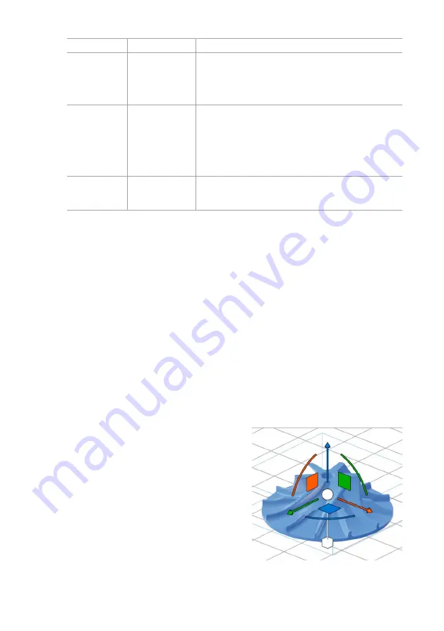
5.3.2.2 Orienting a model
The unsintered powder in the build chamber
inherently supports parts, regardless of their
orientation. However, depending on the
geometry of the parts being printed, certain
part orientations may minimize the visibility of
print layers or to pack parts more densely into a
complete print job.
To orient a model:
1. Select the model using the left mouse button.
Manipulators appear over the model.
Summary of Contents for Fuse 1
Page 1: ...Manual Fuse 1 ...
Page 2: ......
Page 6: ......
Page 64: ...Original English instructions January 2021 Formlabs ...


