


1 - 6
ForeRunner
ATM Switch Network Configuration Manual
Configuring PVCs
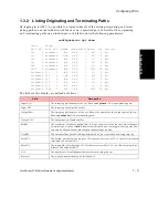
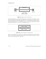
1.2.2 Originating and Terminating Paths
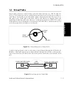
As previously noted, originating and terminating paths (also called virtual path terminators)
are points at which a virtual path originates and terminates. For example, if a virtual path
exists from switch fabric A to switch fabric B, then there must be an originating path on switch
fabric A and a terminating path on switch fabric B.
An originating path is defined by two parameters: output VPI and output port. Similarly, a
terminating path is defined by the parameters: input VPI and input port. Because originating
and terminating paths do not define the way cells are switched through an ATM switch fabric,
virtual channels must exist to switch cells from a terminating path to an originating path. (See
the section about virtual channels for more information.) Originating and terminating paths
are the endpoints of virtual paths and are used primarily for bandwidth allocation.
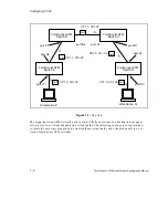
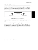
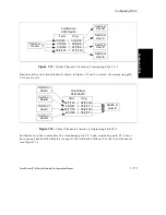
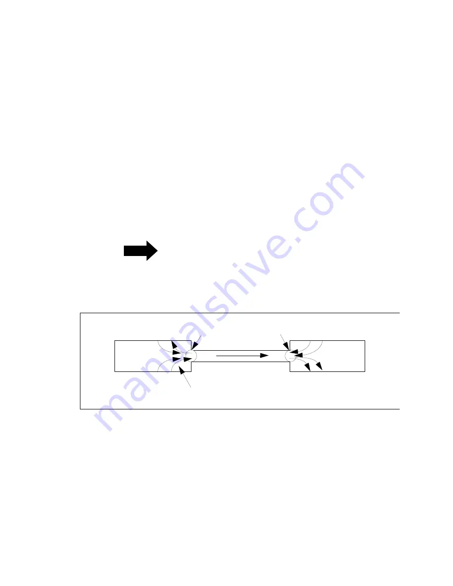
The bandwidth allocated to originating and terminating paths is used to control the amount of
virtual channel (VCC) bandwidth entering or leaving a virtual path. The total guaranteed
bandwidth used by virtual channels on an originating path or a terminating path cannot
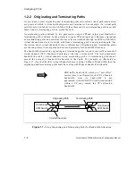
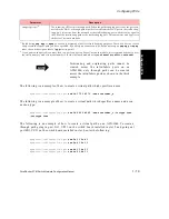
exceed the amount of bandwidth allocated to that path. For example, as illustrated in
Figure 1.7, if each of the four virtual channels shown is using 10 Mbps of bandwidth, then the
originating and terminating paths must have at least 40 Mbps of bandwidth allocated.
NOTE
UBR traffic bandwidth, which is a “best effort”
service class, is not limited by the VP’s allocated
bandwidth since its bandwidth is not
guaranteed. Actual UBR VCC traffic transmitted
within a VP may exceed the VP’s allocated
bandwidth.
Figure 1.7 -
Using Originating and Terminating Paths for Bandwidth Allocation
Virtual Channels
Terminating Path
Originating Path
ForeRunner
ATM Switch
ForeRunner
ATM Switch
Summary of Contents for forerunner series
Page 6: ......
Page 16: ...TOC 10 ForeRunner ATM Switch Network Configuration Manual Table of Contents ...
Page 20: ...LOF 4 ForeRunner ATM Switch Network Configuration Manual List of Figures ...
Page 22: ...LOT 2 ForeRunner ATM Switch Network Configuration Manual List of Tables ...
Page 30: ...viii ForeRunner ATM Switch Network Configuration Manual Preface ...
Page 144: ...3 58 ForeRunner ATM Switch Network Configuration Manual Configuring an Emulated LAN ...
Page 180: ...6 12 ForeRunner ATM Switch Network Configuration Manual ATM Forum PNNI ...
Page 220: ...9 6 ForeRunner ATM Switch Network Configuration Manual Configuring Timing ...
Page 300: ...D 24 ForeRunner ATM Switch Network Configuration Manual Configuring FramePlus Modules ...
Page 308: ...Acronyms 8 ForeRunner ATM Switch Network Configuration Manual Acronyms ...
Page 346: ...Glossary 38 ForeRunner ATM Switch Network Configuration Manual Glossary ...
Page 352: ...Index 6 ForeRunner ATM Switch Network Configuration Manual Index ...


