Centellis CT Series 16000 User’s Manual
Chassis Layout and Interconnection
20000325 420 000 AB
Page 27
3.4.2
J3: Backplane I/O Connector
J3 is a user-defined I/O connector on the Centellis backplane. For pin-out information, consult the
appropriate CompactPCI PICMG specifications.
3.4.3
J4 Backplane I/O Connector
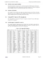
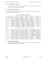
The J4 connector is used for the H.110 bus. This connector is a 220-pin 2 mm x 2 mm female connector for
a 2mm interface. Red keying is used on J4.
3.4.4
J5 Backplane I/O Connector.
J5 is a user-defined I/O connector on the Centellis backplane. For pin-out information, consult the
appropriate CompactPCI PICMG specifications.
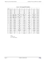
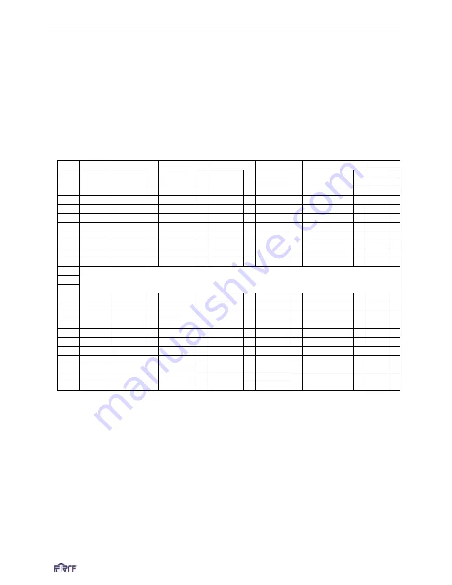
Table 14:
J4: CompactPCI Interface
Pin
Row Z
Row A
Row B
Row C
Row D
Row E
Row F
25
Not Used
SGA4
M
SGA3
M
SGA2
M
SGA1
M
SGA0
M
FG
L
24
"
GA4
M
GA3
M
GA2
M
GA1
M
GA0
M
FG
L
23
"
+12V
M
/CT_Reset
M
/CT_EN
S
-12V
M
CT_MC
M
FG
L
22
"
RSVD
M
RSVD
M
RSVD
M
RSVD
M
RSVD
M
FG
L
21
"
-SELVbat
L
RSVD
M
RSVD
M
RSVD
M
-SELVbatRtn
L
FG
L
20
"
Not Used
Not Used
Not Used
Not Used
Not Used
NP
19
"
Not Used
Not Used
Not Used
Not Used
Not Used
NP
18
"
VRG
M
Not Used
Not Used
Not Used
Not Used
M
NP
17
"
Not Used
Not Used
Not Used
Not Used
Not Used
NP
16
"
Not Used
Not Used
Not Used
Not Used
Not Used
NP
15
"
-Vbat
L
Not Used
Not Used
Not Used
Not Used
L
NP
14
KEY AREA (keep unobstructed on backplane to ease routing constraints)
13
12
11
"
CT_D29
M
CT_D30
M
CT_D31
M
V(I/O)
L
/CT_FRAME_A
M
GND
L
10
"
CT_D27
M
+3.3V
M
CT_D28
M
+5V
L
/CT_FRAME_B
M
GND
L
9
"
CT_D24
M
CT_D25
M
CT_D26
M
GND
L
/FR_COMP
M
GND
L
8
"
CT_D21
M
CT_D22
M
CT_D23
M
+5V
L
CT_C8_A
M
GND
L
7
"
CT_D19
M
+5V
M
CT_D20
M
GND
L
CT_C8_A
M
GND
L
6
"
CT_D16
M
CT_D17
M
CT_D18
M
GND
L
CT_NETREF_1
M
GND
L
5
"
CT_D13
M
CT_D14
M
CT_D15
M
+3.3V
L
CT_NETREF_2
M
GND
L
4
"
CT_D11
M
+5V
M
CT_D12
M
+3.3V
L
SCLK
M
GND
L
3
"
CT_D8
M
CT_D9
M
CT_D10
M
GND
L
SCLKx2
M
GND
L
2
"
CT_D4
M
CT_D5
M
CT_D6
M
CT_D7
M
GND
L
GND
L
1
"
CT_D0
M
+3.3V
M
CT_D1
M
CT_D2
M
CT_D3
M
GND
L


