


Installation
Centellis CT Series 16000 User’s Manual
Page 14
20000325 420 000 AB
2.10.2 Powering Up
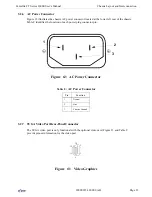
1. Connect the power cable to the AC connector.
2. Turn on each power supply switch. (This is the black switch on each power supply.)
3. Turn on the green power switch at the back of the chassis. After a few seconds, a message
will appear on the connected monitor.
4. Check that the fans work properly and that the LEDs on the boards, if available, indicate
the run status.
5. To boot the installed operating system, see the operating system’s user’s manual.
2.11 Power Supplies
The Centellis CT Series 16000 chassis contains two 300W load-sharing power supplies. The pow-
er supplies are installed at the bottom rear side of the chassis. A green LED on the face of each
power supply lights when a power supply is in use and functioning properly.
If either of the power supplies is malfunctioning, an audible beep will sound from the chassis com-
biner board. (The green LED on the bad power supply will not light.) This alarm continues until
the bad power supply is replaced by a new, working power supply. Ensure that the replacement
power supply’s power switch is turned to the On position; if not, the alarm beep will continue.
A fifteen-prong connector on the back of the power supply connects to the chassis backplane.
See the Centellis Power Supply Installation Instructions (P/N 209652) for complete information on
installing and removing the power supplies.
CAUTION
!
The power supplies are provided with input voltage selector switches. These
switches must be set to the correct voltage for your voltage source (115V or 230V).
Ensure that each power supply is set to the correct voltage.
WARNING
The power supplies must be serviced only by service personnel familiar with the
hazards and dangers associated with switched mode power supplies.