Centellis CT Series 16000 User’s Manual
Installation
20000325 420 000 AB
Page 13
•
For hard disk drives, mount the drive onto the HDD mounting bracket with
a 6/32" x 1/4" Phillips pan head screw, a #6 split lock washer, and a #6 flat washer
at each of the four positions. Do not mount this assembly to the peripheral tray
yet; OR
•
For CD-ROM drives, align the four mounting screw holes on the peripheral
tray and the CD-ROM. Attach the drive to the peripheral tray with
four 3cm
x 6cm pan head screws, four M3 split lock washers, and four M3 flat washers.
3. Attach one end of the flat ribbon cable (the end with two connectors close to each other)
and one end of the power cable to the CD-ROM or hard disk drive.
4. For a hard disk drive, attach the completed drive/HDD mounting bracket assemblage to
the peripheral tray with four 6/32" x 1/4' flat head screws.
5. Reinsert the peripheral tray with the attached drive(s) back into the chassis.
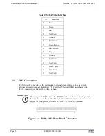
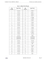
6. Remove the left rear panel, and attach the other end of the flat ribbon cable to the I/O
boards. Route the cables together as directly as possible to avoid cable damage and to save
space for other cables and boards. CAUTION: Pin 1 of the flat ribbon cable (red stripe)
MUST match with Pin 1 of the connector.
7. Retighten the two thumb screws on the tray face plate to secure the tray to the chassis.
2.10 Power-up Procedures
This section explains how to connect chassis peripherals and power up the Centellis chassis. Note
the following CAUTION statements before powering up the unit.
CAUTION
!
Connections between peripherals of the computer equipment must be made with low-
voltage, shielded computer data cables.
CAUTION
!
Do not attach like devices to both the front CPU panel and the rear chassis panel as
damage to components may result.
The Centellis 16000 has CPU board connectors at the front of the chassis as well as I/O connectors
on the chassis back.
2.10.1 Connecting Chassis Peripherals
Peripheral components can be connected to the Centellis chassis at the CPU board in the front of
the chassis, or at the transitional board (if installed) at the back of the chassis. Install the peripher-
als in the following order:
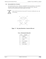
1. Connect an IBM PS/2-style keyboard into the keyboard connection.
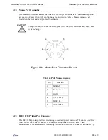
2. Connect a PS/2-style mouse into the mouse connection.
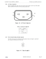
3. If installing an optional SVGA compatible monitor, both the monitor and the Centellis
chassis must be turned off. Connect the video cable to the video port connection.


